
What you will make
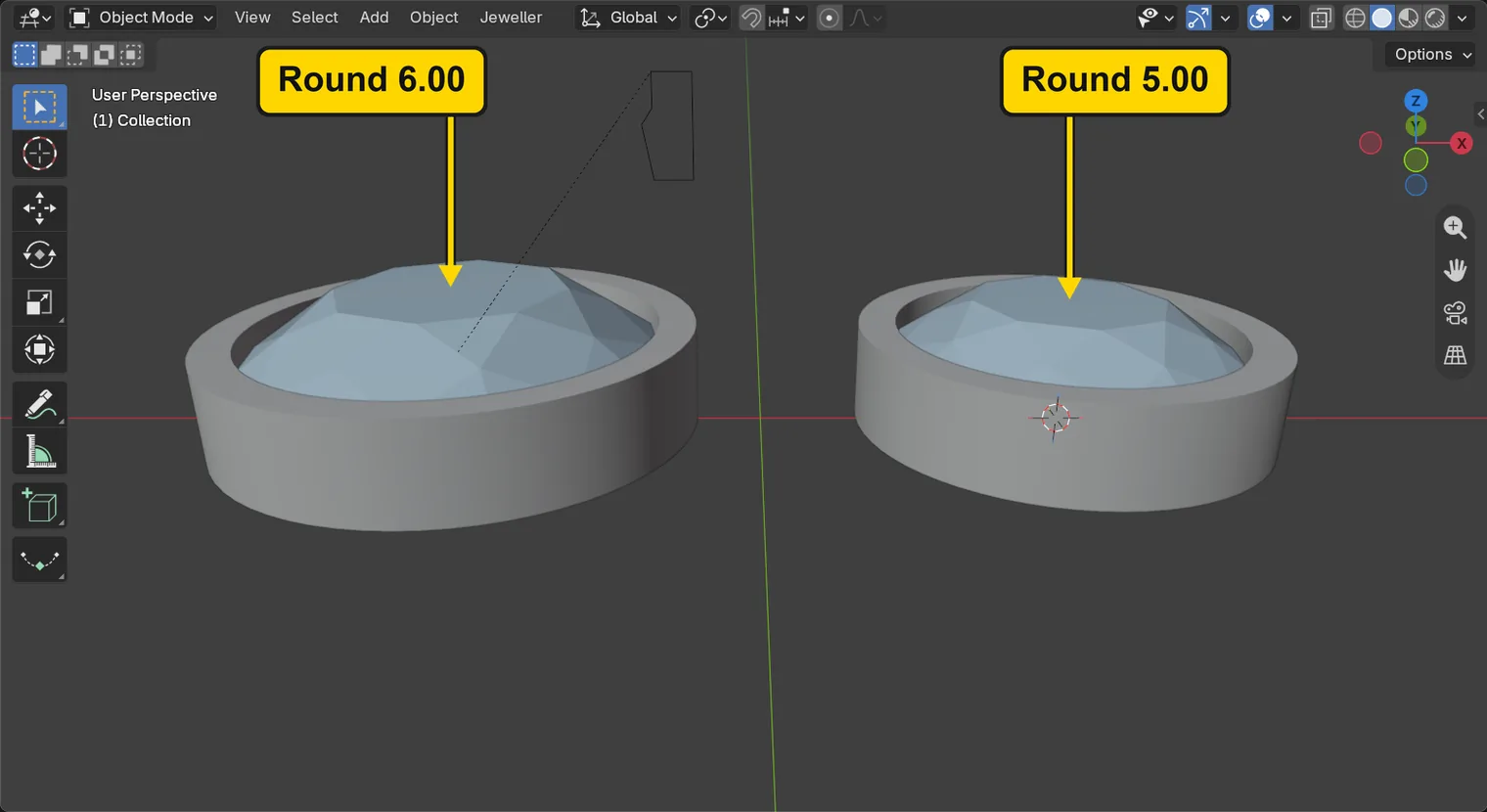
Two stones, a Round 6.00 and a Round 5.00, each in a straight bezel wall made from one shared section. The section is the wall cut through: a small curve beside the first stone, drawn at true size. You move one point of that curve, the outer foot, 0.2 mm outward, and both walls make themselves again at once. You save the shape, put the add-on’s own section back, and press Make Real: each wall becomes a solid of metal that belongs to no setting any more, and that is what goes to a caster. A production file keeps the bench’s own section, and no lip is formed over the crown (the lip is the top edge pushed over the stone, as P5-01 says): the setter pushes the wall’s top over it.
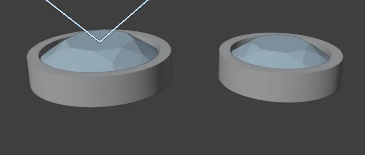
About 15 minutes.
Files
- p5-02-start.blend (123 KB): open this one to begin.
- p5-02-finished.blend (130 KB): the result, to compare with yours.
Both were made in Blender 5.2.0.
Before you start
- You have done Part 0, Blender from nothing, and Set several stones in rub-over with one button (P5-01): the tool, the section and the set’s row are not explained again here.
- CAD/CAM Jeweller 2.22.0 or later (Preferences > Add-ons shows the version). The start file holds a Round 6.00 and a Round 5.00, each in a live bezel wall, in millimetres. Both walls belong to one set and share one section.
- Small pink dots, arrows and squares, and the word Done, may show on a stone once it is selected. They are handles: marks that change a number when you press and drag them. Leave them alone for now: click the stone’s grey top, between the marks. If a number changes after a click, a mark was pressed: press
Esc, thenCtrl+Z.
Build it
Step 1. Open the start file and save your copy
WhereThe top bar: the row of words that begins File, Edit.
DoDownload p5-02-start.blend from Files above and open it. Then choose File > Save As and save it under the name below, in a folder of yours. Open an exercise file and keep the start file safe (P0-07) shows how.
Typemy-section.blend
You should seeThe 3D view shows a Round 6.00 and a Round 5.00 side by side, each inside a straight metal wall, and nothing is selected. The title bar, the strip above File and Edit, begins my-section. The first picture is the 3D view and the second is the title bar.
It worked whenThe title bar, the strip above File and Edit, begins my-section.

Step 2. Click a stone to bring up its set
WhereThe sidebar: press N with the pointer over the 3D view if it is shut. Click the CAD/CAM tab, then Setting in the section bar. The panel is Stone Settings. Then the 3D view.
DoClick the Round 6.00, in the middle of its table, the flat top, between any pink marks.
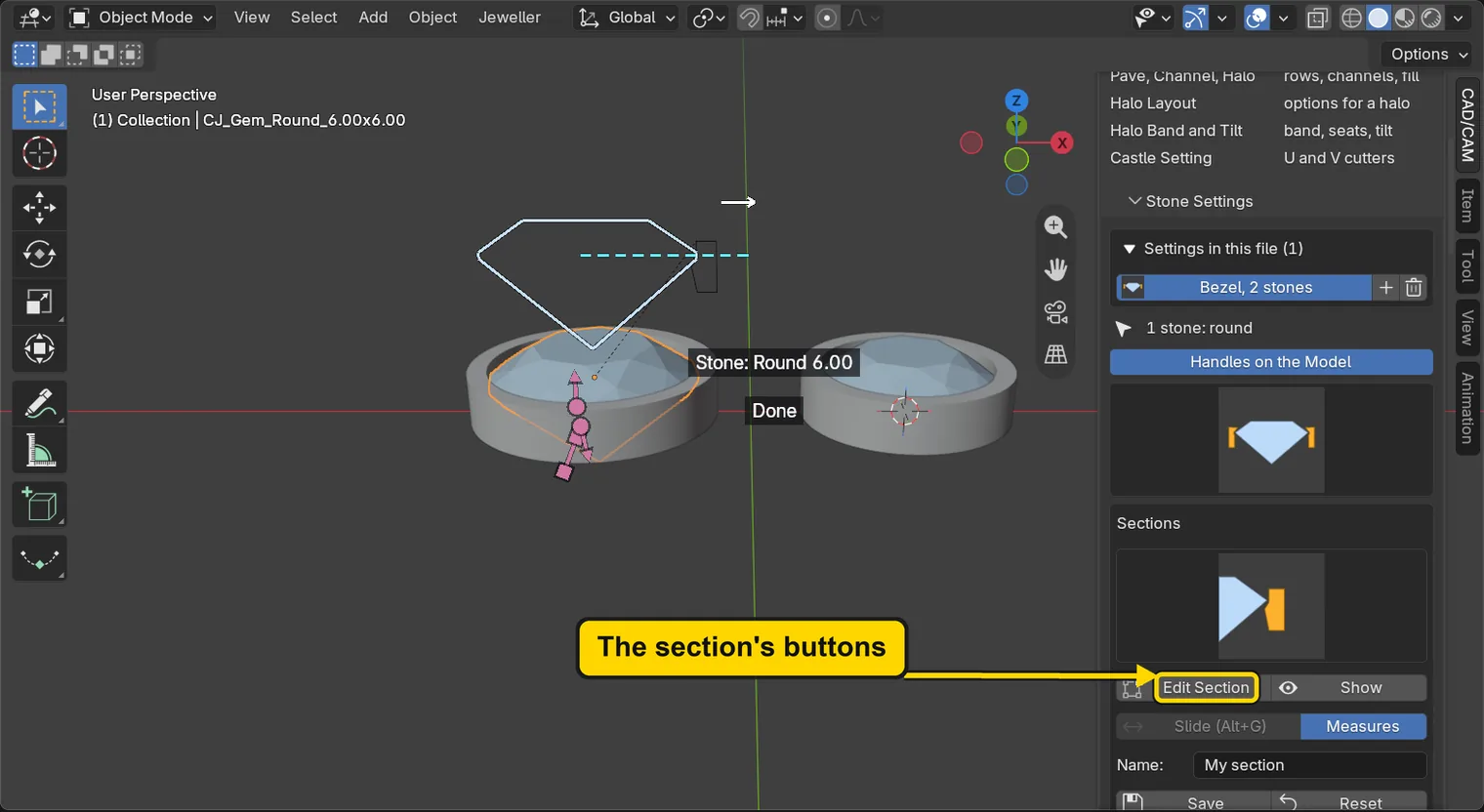
You should seeThe panel shows the set: the row at the top, the picture of the section, the buttons Edit Section, Show, Save and Reset, and under them Wall 0.55 mm, Over the girdle 0.32 mm and Seat 0.15 mm. (0.55 is the bench’s own section for a bezel, under the Standards Check’s own least of 0.60, as P5-01 says.) A small curve stands in the air above the first stone: the section, the wall cut through, drawn at true size.
It worked whenThe panel shows Wall 0.55 mm.
Step 3. Press Show
WhereThe Stone Settings panel, the button Show.
DoPress Show.
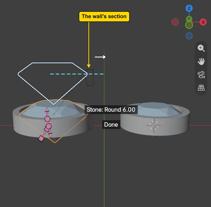
You should seeThe curve stands over the first stone, with its points: the wall’s section, its inner face and its seat on the left, its outside on the right. It is the small dark shape beside the large white diamond. The white diamond is the stone’s own outline, drawn so that the section can be read against it: ignore it, and the dashed blue line (the girdle’s level). Show puts the curve on view if it was hidden. Here it is on view already, so nothing changes.
It worked whenA small curve stands over the Round 6.00.
Step 4. Press Edit Section
WhereThe Stone Settings panel, the button Edit Section.
DoPress Edit Section. Then click the green ball marked -Y at the top right of the 3D view, press A over the 3D view, and choose View > Frame Selected (or two fingers up on a touchpad).
You should seeThe curve alone is selected and Blender is in Edit Mode on it, where you work on one piece’s own points. The words at the top left of the 3D view read Edit Mode and name the curve. A picks every point of the curve, so that Frame Selected brings the whole curve up. The picture shows it from the front, large; choose View > Frame All to come back. The block of white words on the dark panel is the section’s read-out: ignore it, except that for a Round 6.00 the girdle is 0.18 thick, so the wall’s top stands 0.32 over it.
It worked whenThe words at the top left of the 3D view name the curve, and the header reads Edit Mode.
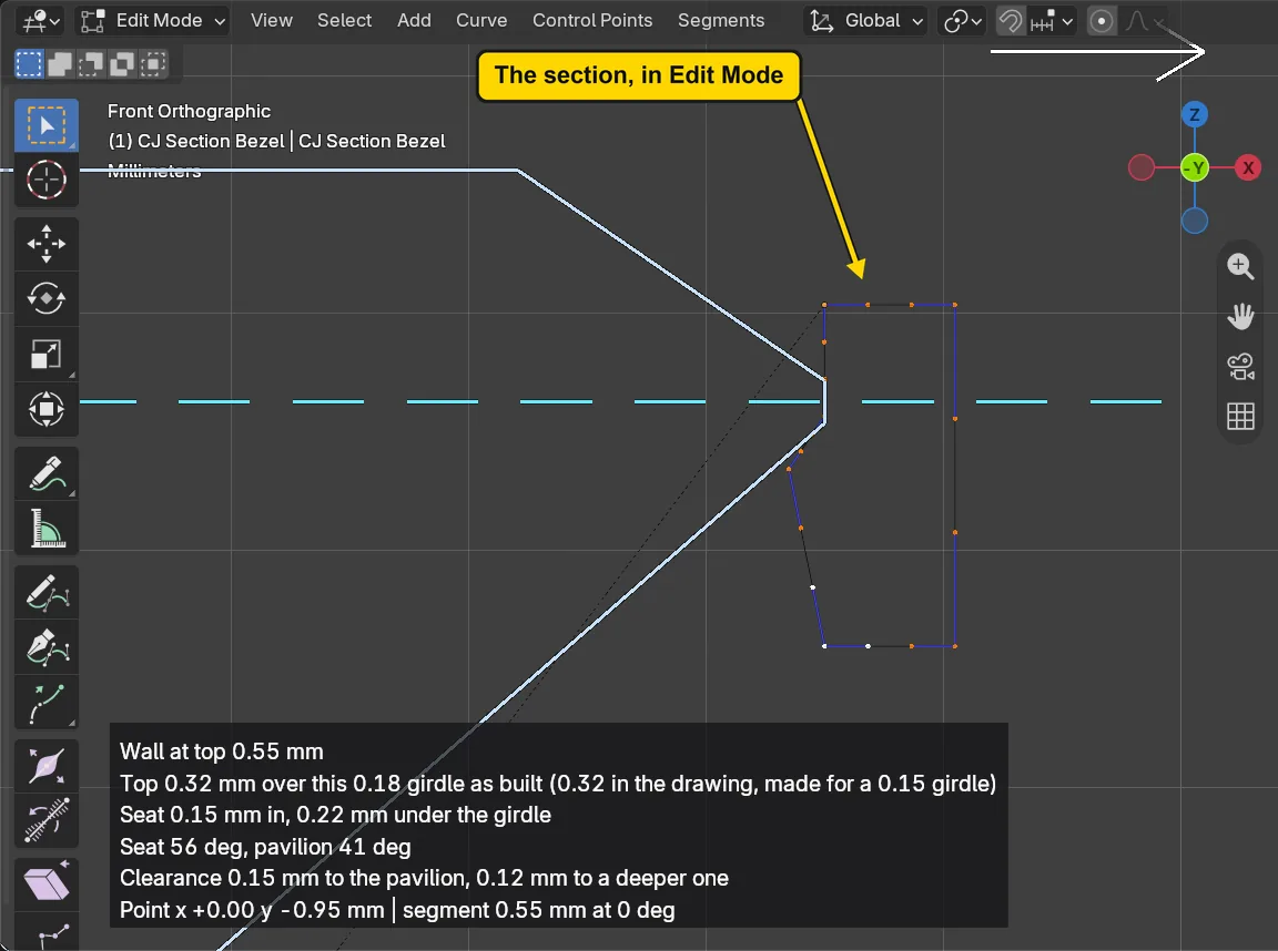
A with the pointer over the 3D view, then choose View > Frame Selected (or two fingers up on a touchpad). The picture is a little tidier than yours will beStep 5. Click the outer foot point
WhereThe 3D view, the section curve: the lowest point on the outside, the right-hand end of the bottom edge.
DoClick that point, the one the second picture marks “Click this point”, then click the Item tab, the tab on the strip down the sidebar’s right edge, under CAD/CAM.
You should seeThe point turns white, with the lines beside it blue: it is the only one picked (the small orange dot at the top of the curve is the curve’s own origin: ignore it). In the sidebar, the Item tab shows it under Control Point:, with its X and Y in the curve’s own measures. X reads 0.55: the wall’s thickness, in millimetres, at its foot.
It worked whenOne point is white, and the Item tab names a Control Point:.
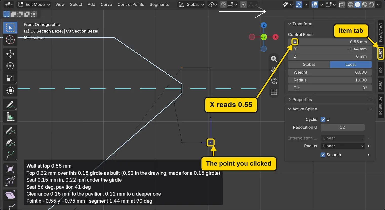
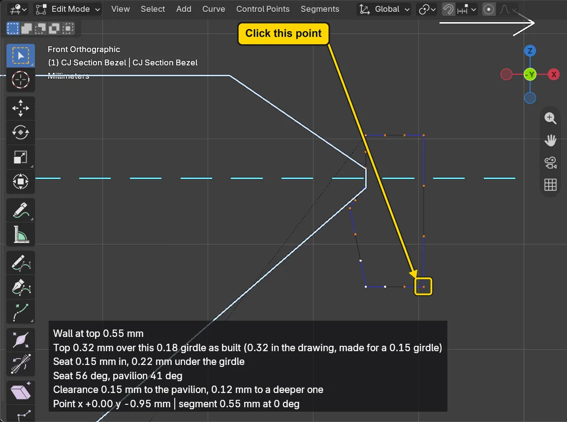
If it goes wrongNo point turns white, or two points do: the click was between points. Click again, right on the point you want.
If it goes wrongThe sidebar is not on the screen: press N with the pointer over the 3D view, then click the Item tab.
Step 6. Move the foot outward
WhereThe 3D view: move the pointer over it, off the sidebar.
DoPress G, then X, then type the distance, then Enter. G starts a move, X keeps it to the X direction, the number is the distance in millimetres, and Enter ends it; Esc backs out.
Type0.2
You should seeThe point moves to the right, away from the stone, and the wall’s outside leans out toward its foot, a wall wider at the foot than at the top. The Item tab’s X reads 0.75 mm, from 0.55.
It worked whenThe Item tab’s X reads 0.75.
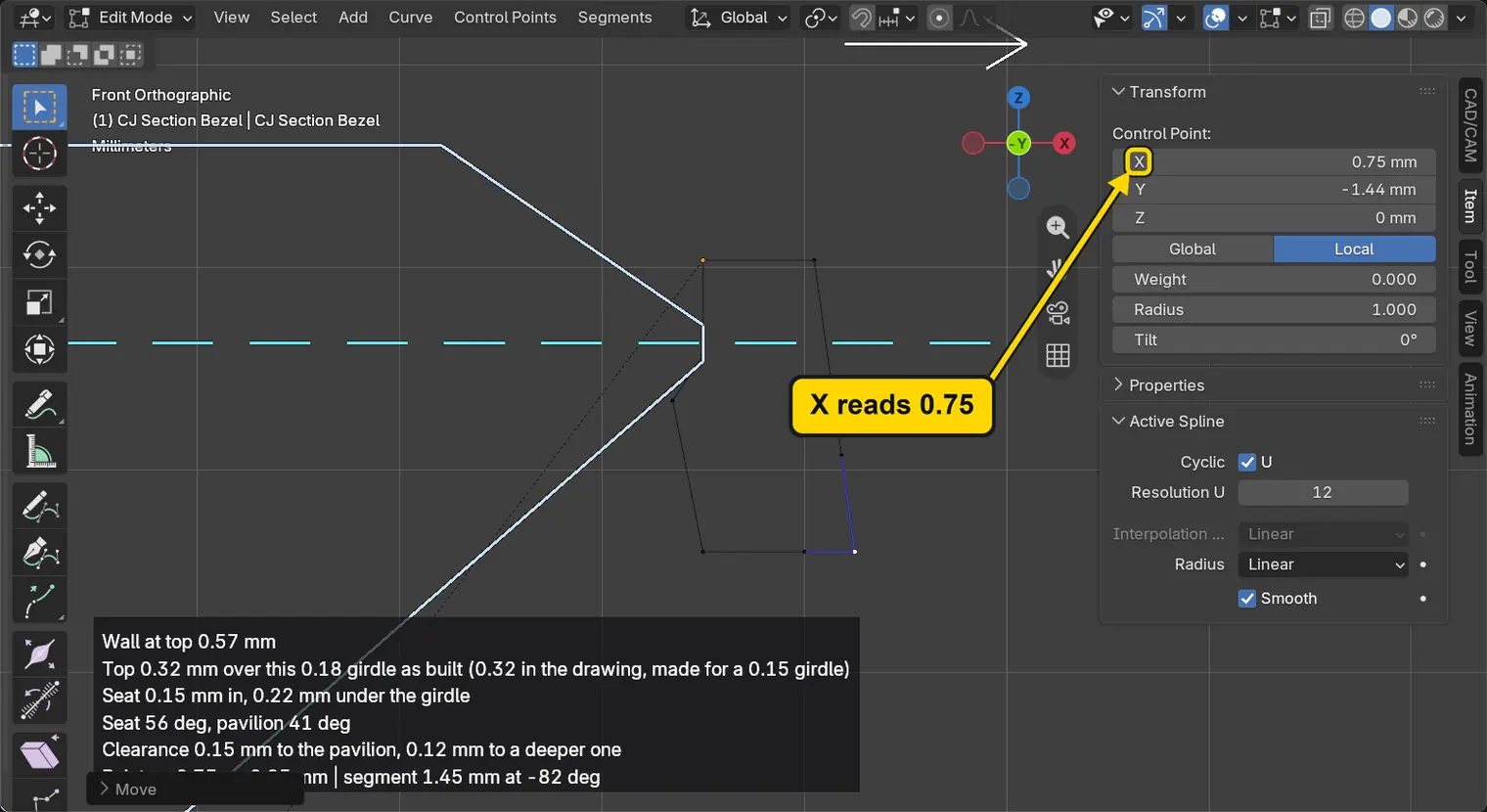
Step 7. Leave Edit Mode and let both walls follow
WhereThe 3D view: the pointer is over it. Then the CAD/CAM tab.
DoPress Tab, then click the CAD/CAM tab to go back from the Item tab.
You should seeEdit Mode ends and both walls make themselves again from the new section, the Round 6.00’s and the Round 5.00’s. Under the buttons the panel says “The section was edited by hand” and greys Wall: a number that changes the shape is held while the shape is your own, and Reset gives it back.
It worked whenThe panel says “The section was edited by hand”.
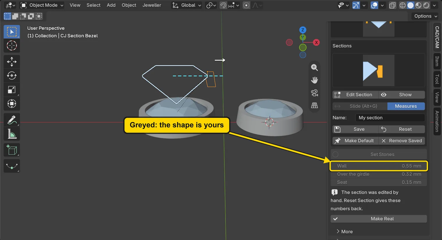
Step 8. Save the section by a name
WhereThe Stone Settings panel: the Name: field, then the button Save.
DoLeave the Name: field as it is, then press Save.
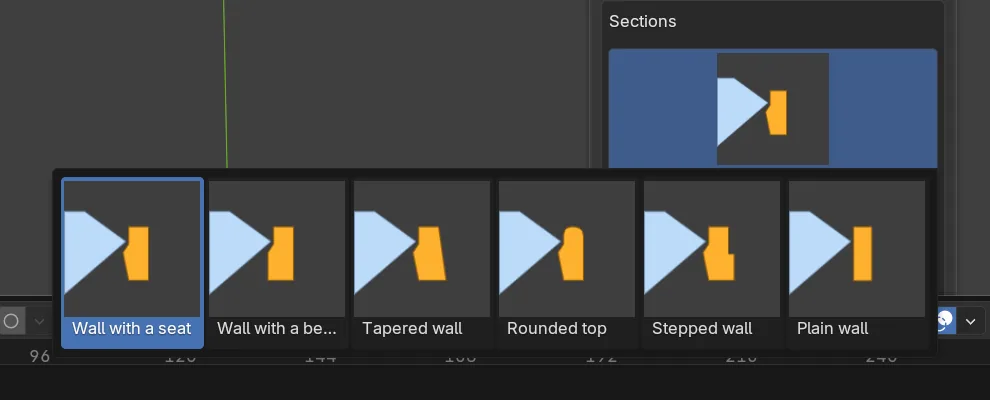
You should seeThe field marked 1 in the picture reads “My section”: the name the section is saved under. The shape is kept by that name for every file you open on this computer. To see it on the list, click the section picture in the box Sections to open the grid: My section stands after the six starts, as the second picture shows. Press Esc to shut the grid without choosing. The wall in the file does not change.
It worked whenThe saved shape is on the list of sections, under My section.
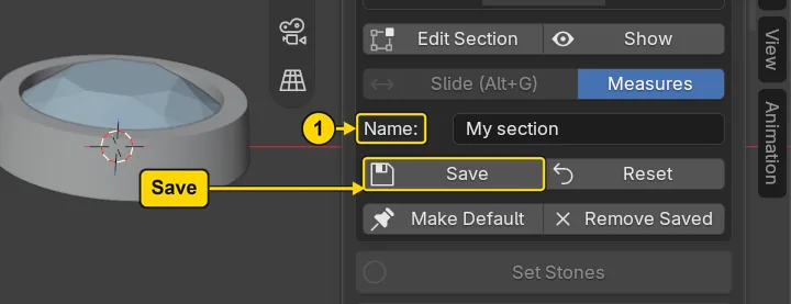
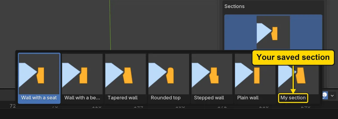
Step 9. Press Reset
WhereThe Stone Settings panel, the button Reset.
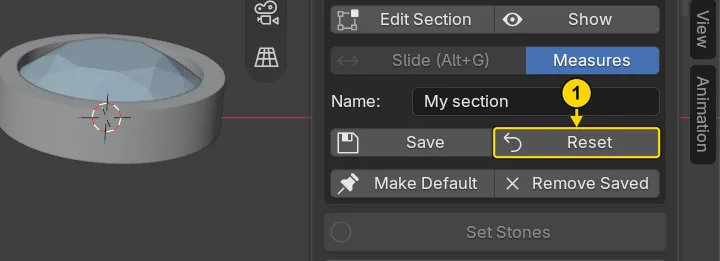
DoPress Reset.
You should seeThe picture marks Reset with a 1. The curve is the add-on’s own start again, and both walls make themselves again at once. The saved name stays on the list, and the greyed Wall is live again.
It worked whenThe walls stand straight again and Wall is no longer grey.
Step 10. Remove the saved name
WhereThe Stone Settings panel, the button Remove Saved.
DoPress Remove Saved: the Name: field still holds the name.
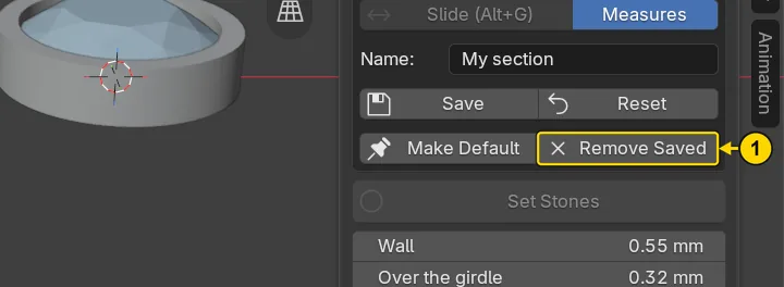
You should seeThe picture marks Remove Saved with a 1. The name leaves the list of sections: open the grid again, as in step 8, and it holds the six starts only, as the second picture shows. Remove Saved takes a saved shape off the list and touches nothing else: both walls stay as they are.
It worked whenThe saved name is off the list.
Step 11. Make the walls real
WhereThe Stone Settings panel, the button Make Real, under the numbers. Scroll the sidebar down to it.
DoPress Make Real.
You should seeThe status bar says “2 solids made.” for a moment, as the second picture shows. Each wall becomes a solid of its own, named for its stone and ending in real: 2 of them. A solid is a closed shape of metal that a caster can use. The live walls and their section stay in the file, so that the set can be made again. No lip has been formed over either crown: the walls are the bench’s own section, straight, and the setter pushes the tops.
It worked whenThe Outliner, the list at the top right of the window, has two new rows ending in real (the list is narrow, so the names are cut short: widen it by dragging the line under it to see the ends).

Step 12. Save your work
WhereThe 3D view: move the pointer over it.
DoPress Ctrl+S.
You should seeBlender writes your copy at once, with no question, because the file already has a name. An asterisk, *, in the title bar marks changes that are not saved, and it goes now. Save your work and get it back (P0-12) says more about saving.
It worked whenThe title bar begins my-section and carries no asterisk.
No picture: the only change is a message on the status bar, and it fades.
Check your result
| What to read | Where | What it should say |
|---|---|---|
| The foot point | The Item tab of the sidebar, in Edit Mode on the section, Control Point: X | It reads 0.75 mm at step 6, from 0.55 at step 5 |
| Both walls follow | The 3D view and the panel, after step 7 | Both walls lean out toward their feet, and the panel says “The section was edited by hand”. (Read by the run from the walls’ own meshes: the Round 6.00’s foot reaches 3.75 mm from its stone’s middle and the Round 5.00’s 3.25 mm, each 0.2 mm further than before, 3.55 and 3.05) |
| The section is back | The 3D view and the panel, after step 9 | The walls stand straight again and Wall is no longer grey. (Read by the run: the feet reach 3.55 and 3.05 mm, the start again) |
| One solid for each stone | The Outliner, the list at the top right of the window, after step 11 | Two new rows, each named for its stone and ending in real: 2 in all (the names are cut short in the narrow list) |
Try it yourself
Open your copy and press Show, then Edit Section, and move the top outer point of the curve inward by 0.10 instead: the wall leans in toward its top, a tapered wall. Look at the number under Wall: it is greyed, because the shape is now your own. Press Reset to get the number back.
What you learned
- Show puts the section’s curve on view and Edit Section opens it for its points. One edit reaches every wall of the set.
- Save keeps a shape by a name for every file, Reset puts the add-on’s own start back, and Remove Saved takes a name off the list. A production file uses the bench’s own section.
- Make Real turns each wall into a solid of its own, and the live walls stay in the file so that the set can be made again. The next page, The older quick route to a rub-over, for a picture (P5-03), shows the older tool.