
What you will make
A plate sitting at the world origin, where the red and green lines cross at the grid’s middle, with the object’s origin, its small dot, in its own middle, and its size set to 30 by 20 by 1.2 mm, from 31.4 by 21.0 by 1.2 mm. A jeweller puts a part at a known place and a known size before building anything on it: the object’s origin is the point every move and every copy measures from. Nothing here cuts or changes the shape of the plate.
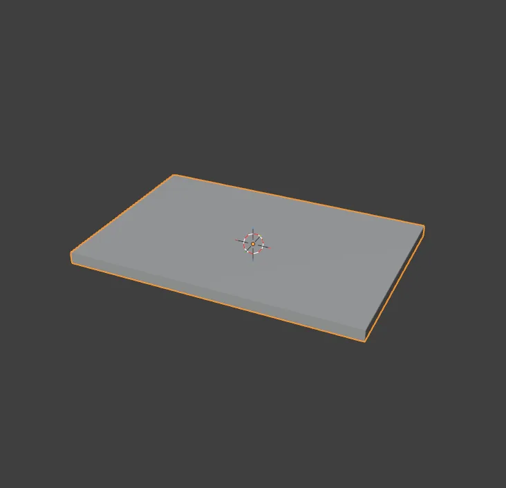
About 10 minutes.
Files
- p2-06-start.blend (99 KB): open this one to begin.
- p2-06-finished.blend (104 KB): the result, to compare with yours.
Both were made in Blender 5.2.0.
Before you start
- You have done Measure a plate with the Ruler (P2-05): you know the CAD/CAM tab and its section bar.
- The add-on is installed. The start file is in millimetres and holds a plain plate that stands off to one side of the grid.
Build it
Step 1. Open the start file and save your copy
WhereThe top bar: the row of words that begins File, Edit.
DoDownload p2-06-start.blend from Files above and open it. Then choose File > Save As and save it under the name below, in a folder of yours. Open an exercise file and keep the start file safe (P0-07) shows how.
Typemy-plate-placed.blend
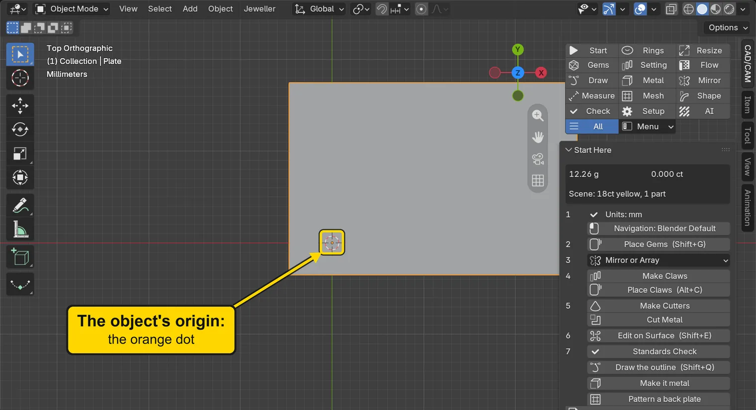
You should seeThe 3D view shows a flat plate seen from above, off to the right of the middle of the grid. The small orange dot near its lower left is the object’s origin, the point the plate’s place is measured from. The world origin is where the red and green lines cross, at the grid’s middle. The words at the top left of the 3D view begin Top Orthographic and end with Plate.
It worked whenThe title bar, the strip above File and Edit, begins my-plate-placed.
Step 2. Open the Shape section and read the Centre and Size panel
WhereThe sidebar: the CAD/CAM tab, then Shape in the section bar.
DoClick the CAD/CAM tab, then click Shape in the section bar.
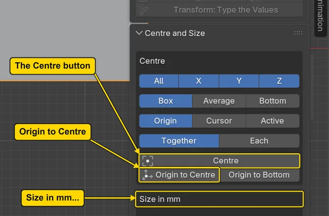
You should seeThe Centre and Size panel. In its first box, Centre, the blue buttons are already set: leave them. The button Centre moves the part. Origin to Centre and Origin to Bottom stand beside it. In the box Size in mm, the button Size in mm… opens a window.
It worked whenThe panel Centre and Size shows the buttons Centre, Origin to Centre, Origin to Bottom and Size in mm….
Step 3. Press Centre
WhereThe Centre and Size panel, the Centre button.
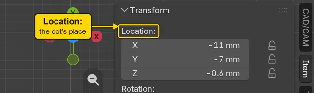
DoPress Centre. Then click the Item tab, the strip of tabs at the right edge of the sidebar, and read Location:. Then click the CAD/CAM tab to come back.
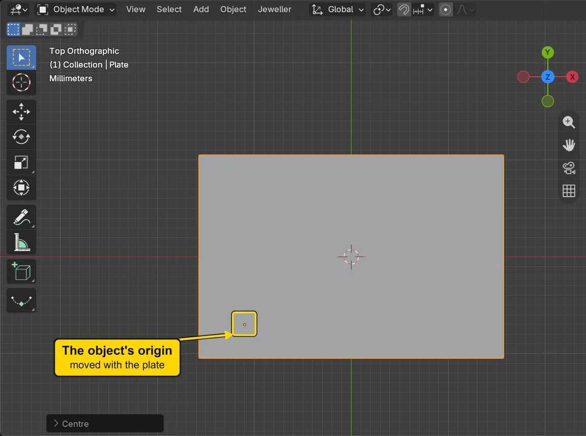
You should seeThe plate moving to the middle of the grid: the middle of its box now stands on the world origin, where the red and green lines cross. The object’s origin, its small dot, did not stay at the plate’s middle: it moved with the plate and now stands off to its lower left. The panel writes one sentence of what it did. The small box at the bottom left, headed Centre, is Blender’s Adjust Last Operation box: leave it alone.
It worked whenThe plate is in the middle of the grid, and the Item tab reads Location: -11.0, -7.0, -0.6 mm.
Step 4. Press Origin to Bottom
WhereThe Centre and Size panel, the Origin to Bottom button.
DoPress Origin to Bottom. Then click the Item tab and read Location:. Then click the CAD/CAM tab to come back.
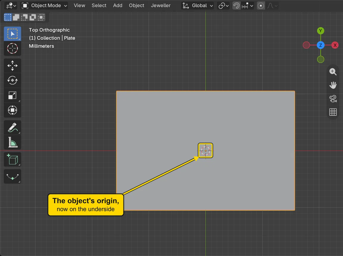
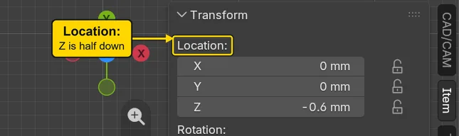
You should seeThe object’s origin, the orange dot, jumping to the middle of the plate’s underside. The plate itself does not move: only the dot does. Location: now reads Z -0.6: the object’s origin is on the underside, which is 0.6 mm below the middle.
It worked whenThe Item tab reads Location: 0, 0, -0.6 mm.
Step 5. Press Origin to Centre
WhereThe Centre and Size panel, the Origin to Centre button.
DoPress Origin to Centre, then click the Item tab and read Location:. Then click the CAD/CAM tab to come back.
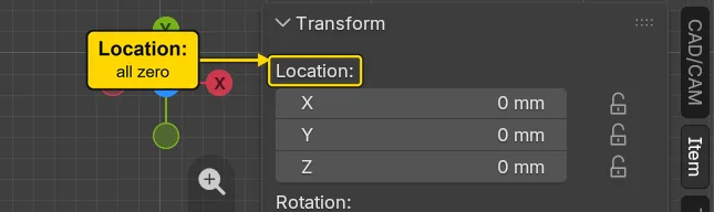
You should seeThe object’s origin, the orange dot, moving to the middle of the plate. Location: reads 0 mm, 0 mm, 0 mm: the plate’s middle stands on the world origin and the object’s origin is at its middle, so the two meet.
It worked whenLocation: reads X 0 mm, Y 0 mm, Z 0 mm.
Step 6. Press Size in mm…
WhereThe Centre and Size panel, the box Size in mm, the button Size in mm…: scroll the sidebar down to it.
DoPress Size in mm…. Leave the pointer where it is.
You should seeA window headed Size in mm opens over the screen. It holds the plate’s size on each axis, 31.4 mm, 21 mm and 1.2 mm, in three fields under New Size:, then Lock Proportions, Pivot and the buttons OK and Cancel. Leave the Set Size switch at the top (it is the blue one of the two) and the Into the Mesh tick as they are: you press OK at the foot. Nothing changes until you press OK. Lock Proportions is ticked: while it is, typing one size makes the other two follow, so that the plate keeps its shape.
It worked whenThe window headed Size in mm is open, with OK and Cancel at its foot.
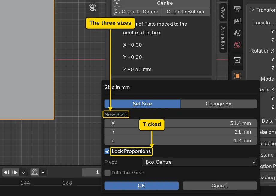
Step 7. Untick Lock Proportions
WhereThe Size in mm window: the box Lock Proportions.
DoClick Lock Proportions so that its tick goes.
You should seeThe tick gone, and a tooltip, the small label that opens when the pointer rests on a button, that reads “Typing one axis scales all three by the same share.”: that is what the tick did. Each size is now its own: the new plate is 30 by 20, and the old one was 31.4 by 21, which is not the same shape, so the sizes cannot follow each other.
It worked whenThe box Lock Proportions has no tick.
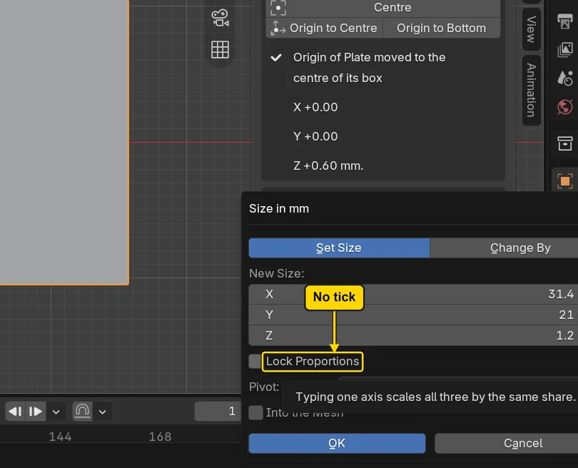
Step 8. Type the three sizes and press OK
WhereThe Size in mm window: the three fields under New Size:.
DoClick the first field, type 30, press Tab, type 20, press Tab, type 1.2, press Enter, then press OK.
Type30, Tab, 20, Tab, 1.2, Enter
You should seeThe window shut and the plate resized: 30 mm by 20 mm by 1.2 mm. Tab moves to the next field, and Enter accepts the last one. The thickness stays 1.2. The panel writes one sentence of what it did, which begins “Size of Plate”. The plate’s middle did not move: Pivot is the point the plate grows or shrinks from, and here it was Box Centre, the middle of the plate.
It worked whenThe panel’s sentence begins “Size of Plate”.
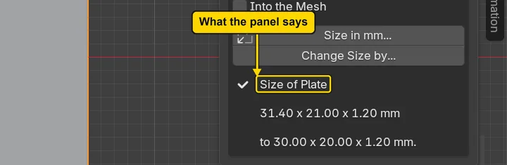
If it goes wrongThe other sizes change as you type: Lock Proportions is still ticked. Press Cancel, press Size in mm… again and untick it first.
Step 9. Read the plate’s place and size in the Item tab
WhereThe sidebar: click the Item tab on its edge, below CAD/CAM.
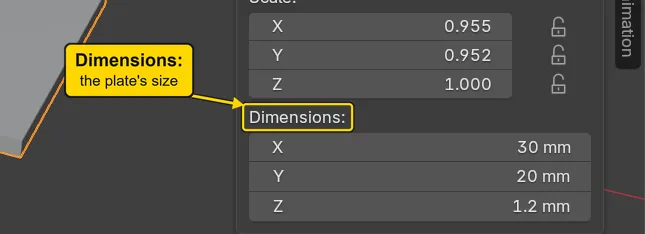
DoClick the Item tab and read Location: and Dimensions:. Then click the CAD/CAM tab to come back.
You should seeLocation: reads X 0 mm, Y 0 mm, Z 0 mm and Dimensions: reads X 30 mm, Y 20 mm, Z 1.2 mm: the plate stands at the middle of the grid, with the object’s origin at its middle, at the size you typed. Scale: no longer reads 1: Size in mm… works through the plate’s Scale, and that is normal. Dimensions: is the size to read.
It worked whenDimensions: reads X 30 mm and Y 20 mm.
Step 10. Save your work
WhereThe 3D view: move the pointer over it.
DoPress Ctrl+S.
You should seeBlender writes your copy at once, with no question, because the file already has a name. An asterisk, *, in the title bar marks changes that are not saved, and it goes now. Save your work and get it back (P0-12) says more about saving.
It worked whenThe title bar begins my-plate-placed and carries no asterisk.
No picture: the only change is a message on the status bar, and it fades.
Check your result
| What to read | Where | What it should say |
|---|---|---|
| Where the plate is | The Item tab of the sidebar, Location: | X 0 mm, Y 0 mm, Z 0 mm |
| The plate’s size | The Item tab, Dimensions: | X 30 mm, Y 20 mm, Z 1.2 mm |
| What the panel said | The CAD/CAM tab, Shape section, the line the Centre and Size panel writes after a press | It names the size it made: 30.00 x 20.00 x 1.20 mm |
Try it yourself
Open your copy again. Press Origin to Bottom and read Location: in the Item tab: Z is now minus half the plate’s thickness. Then press Size in mm…, check that Lock Proportions has its tick, type 15 in the X field, and press OK: the plate halves in every direction, to 15 by 10 by 0.6 mm. That is 0.60 thick: do not keep it.
What you learned
- Centre moves the part so that the middle of its box stands on the world origin, where the red and green lines cross. Origin to Centre and Origin to Bottom move only the object’s origin, its small dot, and leave the shape where it is.
- The object’s origin is the point a move, a turn and a copy are measured from. Location: reads where it stands.
- Size in mm… sets a size by typing millimetres on each axis. Lock Proportions makes the other axes follow the first, so untick it when each size is its own.