
What you will make
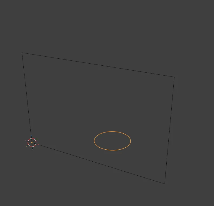
Two drawings at their exact size: a rectangle 30 mm across and 20 mm high, standing upright, and a circle 8 mm across, lying flat on the ground. A jeweller draws a shape at its true size first, because the wire, strip or plate that comes later takes its size from the drawing.
About 10 minutes.
Files
- p2-01-start.blend (98 KB): open this one to begin.
- p2-01-finished.blend (105 KB): the result, to compare with yours.
Both were made in Blender 5.2.0.
Before you start
- You have done Part 0, Blender from nothing, including Work in millimetres (P0-20) and Look from the front, top and right with no number pad (P0-06).
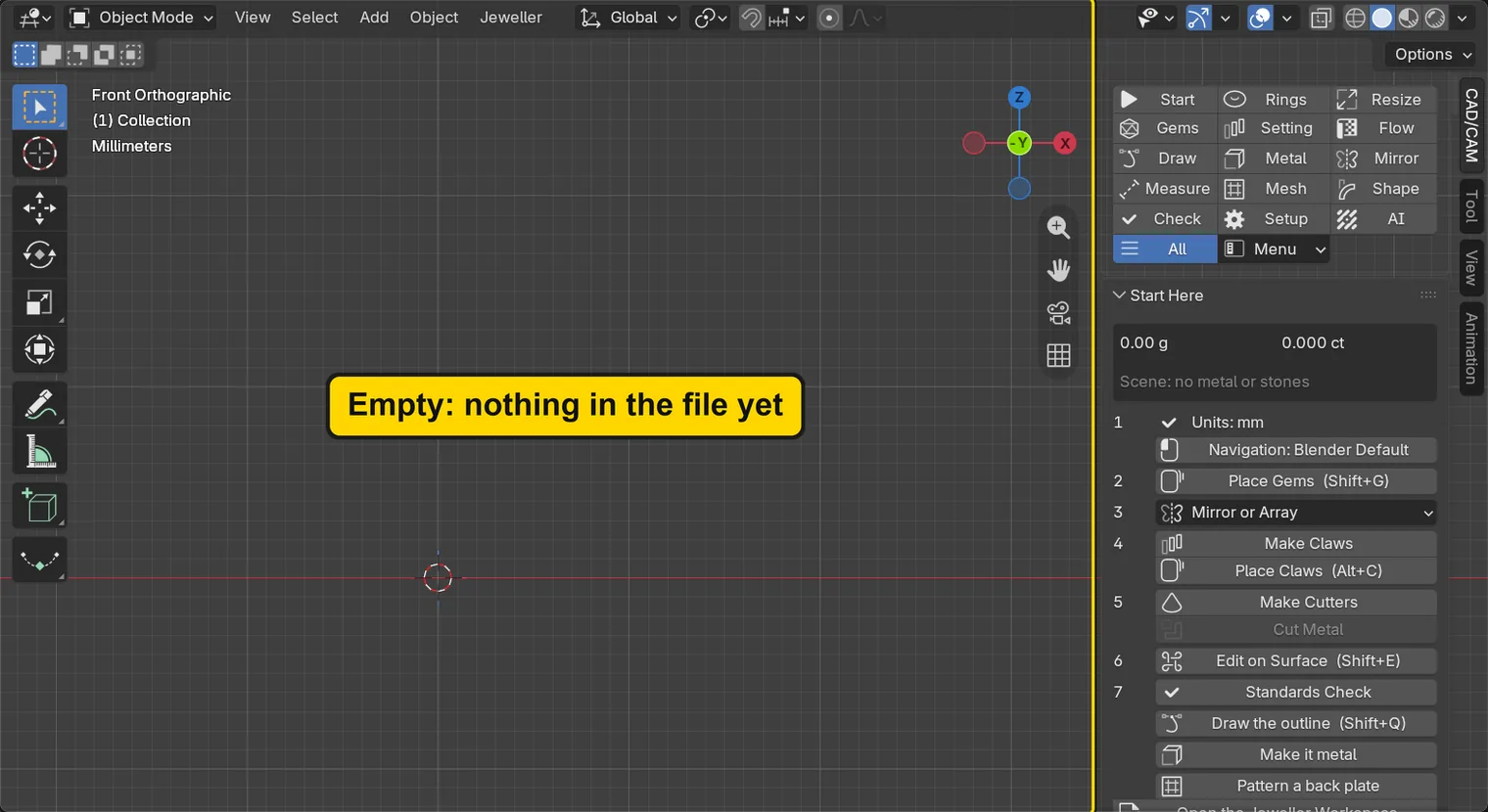
- The add-on is installed, and its CAD/CAM tab is in the sidebar. The start file is empty, already in millimetres, and already looks straight at the front.
Build it
Step 1. Open the start file and save your copy
WhereThe top bar: the row of words that begins File, Edit.
DoDownload p2-01-start.blend from Files above and open it. Then choose File > Save As and save it under the name below, in a folder of yours. Open an exercise file and keep the start file safe (P0-07) shows how.
Typemy-first-drawings.blend
You should seeThe 3D view shows only the grid: nothing is in the file. The words at the top left of the 3D view begin Front Orthographic, so the view looks straight at the front.
It worked whenThe title bar, the strip above File and Edit, begins my-first-drawings.
Step 2. Open the Draw section and read the plane
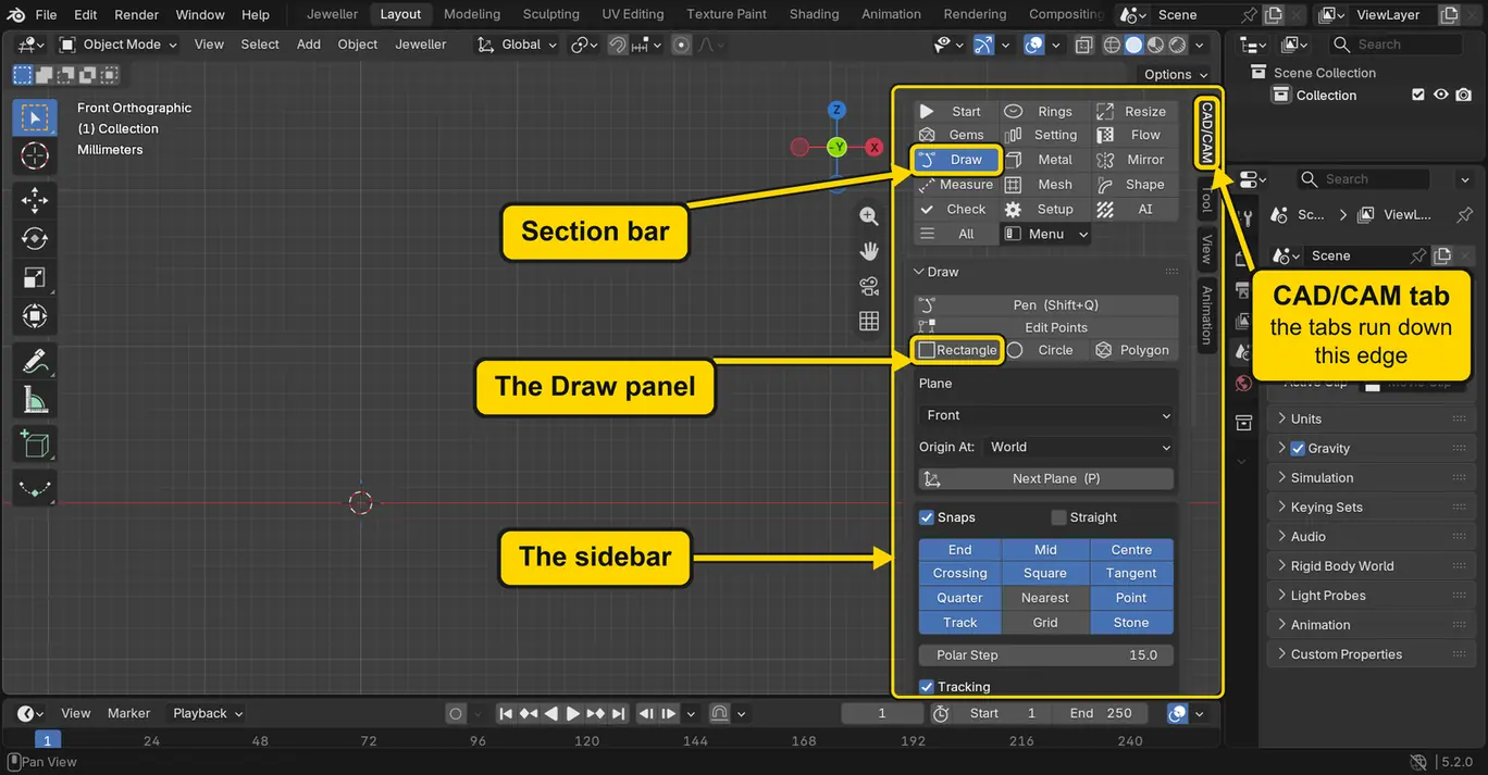
WhereThe sidebar, at the right of the 3D view. If you cannot see it, put the pointer over the 3D view and press N.
DoClick the CAD/CAM tab, then click Draw in the section bar.
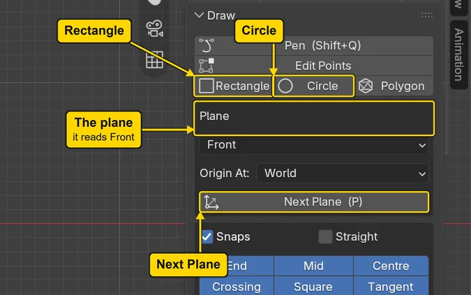
You should seeThe Draw panel, with the drawing buttons Pen, Edit Points, Rectangle, Circle and Polygon, and a box headed Plane that reads Front. The plane is the flat surface a drawing is made on: Front stands upright, facing you, with X across and Z up. Next Plane steps to the next one. The first picture marks the sidebar, its tabs (their names run sideways down its right edge: CAD/CAM is yours; an Item tab joins them in step 5, once a drawing exists), the section bar, the small word buttons at the top of the tab, and the panel. Later pictures often leave the sidebar out, so that the drawing shows larger.
It worked whenThe box headed Plane reads Front.
Step 3. Press Rectangle
WhereThe Draw panel, the Rectangle button.
DoPress Rectangle. Nothing is drawn yet.
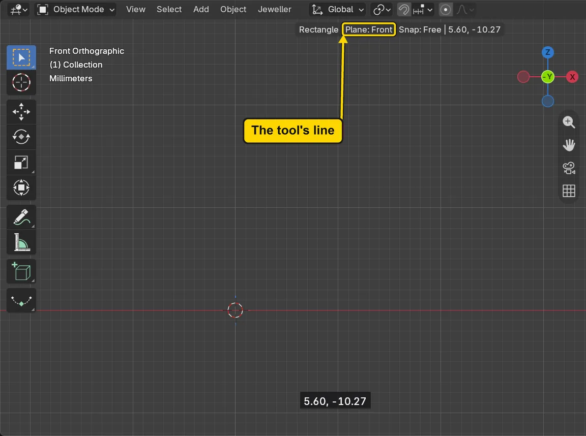
You should seeA line of words just under the header, the row that begins View, Select, Add: the tool’s line. It begins “Rectangle”, then names the plane and the snap, and it takes the place of the header’s small buttons. The tool runs now until you press Enter, which makes the drawing, or Esc, which stops the tool and draws nothing. The numbers beside the pointer show where it is and how far it has moved: you need not match them.
It worked whenThe tool’s line begins “Rectangle”.
Step 4. Type the size and press Enter
WhereThe 3D view: put the pointer on the 3D cursor, the red and white ring on the red line, at the middle of the grid.
DoPut the pointer on the 3D cursor and type 30x20, then press Enter.
Type30x20
You should seeA rectangle with its bottom left corner on the 3D cursor, 30 mm across and 20 mm high. The x between the two numbers is the letter x. The first corner is wherever the pointer stands when you press Enter; the size is exactly what you typed. The tool’s line goes back to the header’s small buttons.
It worked whenA rectangle stands in the 3D view, and the tool’s line has gone back to the header’s small buttons.
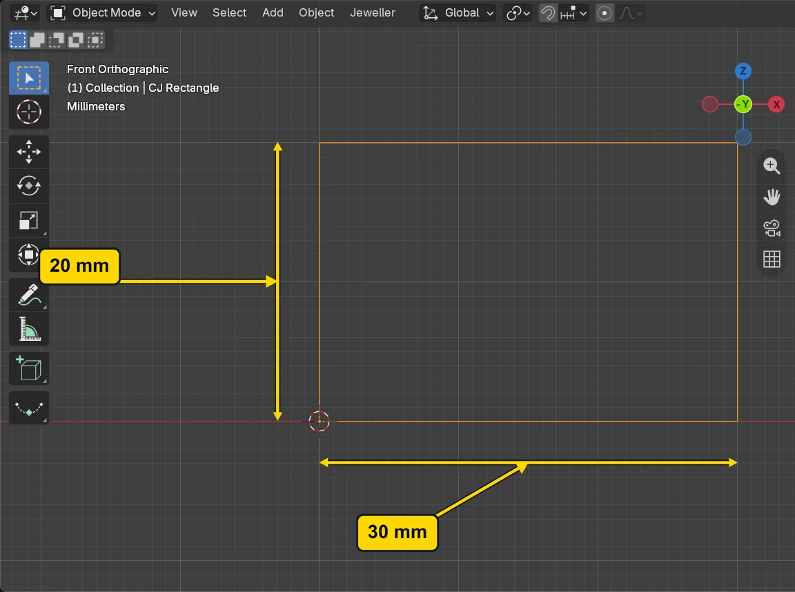
If it goes wrongThe rectangle starts away from the 3D cursor: The pointer was not on it. Press Ctrl+Z, press Rectangle again and put the pointer on the cursor before you type.
Step 5. Read the rectangle’s size in the Item tab
WhereThe sidebar: click the Item tab, the strip of tabs at the right edge of the sidebar, below CAD/CAM.
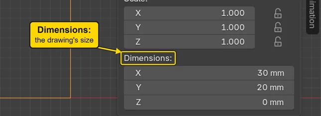
DoClick the Item tab and read Dimensions:. Then click the CAD/CAM tab to come back.
You should seeDimensions: reads X 30 mm, Y 20 mm, Z 0 mm. A drawing has no thickness, so Z is 0. The rectangle stands upright, yet it reads as 20 in Y: Dimensions: measures along the drawing’s own axes, not along the grid. The rectangle is the active drawing, so its size shows.
It worked whenDimensions: reads X 30 mm and Y 20 mm.
Step 6. Press Next Plane twice
WhereThe Draw panel, the Next Plane button.
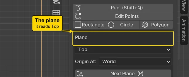
DoPress Next Plane, read the box headed Plane, then press Next Plane again.
You should seeThe box headed Plane read Side after the first press and now reads Top after the second. Top is the plane that lies flat, like a table, with X across and Y away from you. The rectangle you drew stays where it is: a drawing keeps the plane it was made on.
It worked whenThe box headed Plane reads Top.
Step 7. Look from above
WhereThe header, the row of words along the top of the 3D view: View.
DoChoose View > Viewpoint > Top.
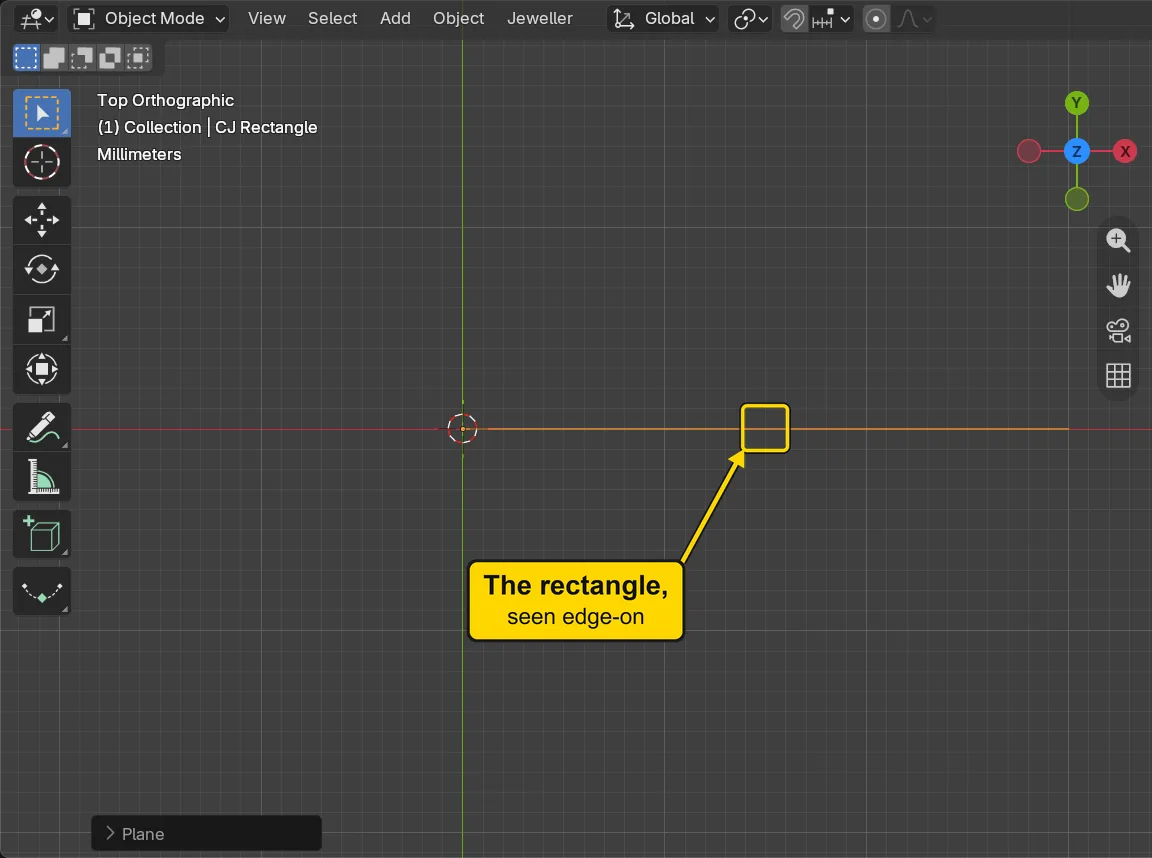
You should seeThe 3D view looking straight down on the ground, and the words at the top left begin Top Orthographic. The rectangle, which stands upright, is now a single line along the X axis: you see it edge-on. A drawing on the Top plane lies in the view you now have. The small box at the bottom left, headed Plane, is Blender’s Adjust Last Operation box: leave it alone.
It worked whenThe words at the top left of the 3D view begin Top Orthographic.
Step 8. Press Circle, then type its size
WhereThe Draw panel, the Circle button. Then the 3D view: put the pointer on an empty place above the line.
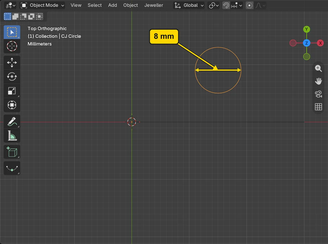
DoPress Circle, put the pointer above the middle of the line, type d8, then press Enter.
Typed8
You should seeA circle with its middle where the pointer stood, 8 mm across. The d stands for diameter, the width right across. r4 would draw the same circle by its radius, the distance from the middle to the edge.
It worked whenA circle stands above the line, and the tool’s line has gone back to the header’s small buttons.
Step 9. Read the circle’s size in the Item tab
WhereThe sidebar: click the Item tab.
DoClick the Item tab and read Dimensions:. Then click the CAD/CAM tab to come back.
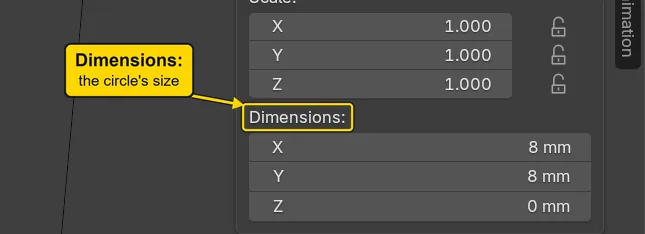
You should seeDimensions: reads X 8 mm, Y 8 mm, Z 0 mm. Again Z is 0: a drawing has no thickness.
It worked whenDimensions: reads X 8 mm and Y 8 mm.
Step 10. Save your work
WhereThe 3D view: move the pointer over it.
DoPress Ctrl+S.
You should seeBlender writes your copy at once, with no question, because the file already has a name. An asterisk, *, in the title bar marks changes that are not saved, and it goes now. Save your work and get it back (P0-12) says more about saving.
It worked whenThe title bar begins my-first-drawings and carries no asterisk.
No picture: the only change is a message on the status bar, and it fades.
Check your result
| What to read | Where | What it should say |
|---|---|---|
| The rectangle’s size | The Item tab of the sidebar, under Dimensions:, with the rectangle selected | X 30 mm, Y 20 mm, Z 0 mm |
| The circle’s size | The Item tab, with the circle selected | X 8 mm, Y 8 mm, Z 0 mm |
| The plane | The CAD/CAM tab, Draw section, the box headed Plane | It reads Top |
Try it yourself
Open your copy again, go to the Draw section and press Rectangle. Type c first (c for centre), then 20x10, then Enter: the new rectangle is drawn out from the pointer as its centre, not from a corner. Press Ctrl+Z to take it back.
What you learned
- A drawing tool in the Draw section runs until you press
Enter, which makes the drawing, orEsc, which draws nothing. Type its size, such as30x20ord8, beforeEnterand the drawing is exactly that size. - A drawing sits on a plane: Front stands upright, Top lies flat. Next Plane steps from one to the next.
- The Item tab’s Dimensions: reads the size of what you drew, in millimetres.