
What you will make
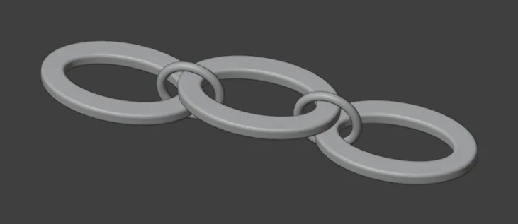
A section of an oval-link bracelet in 18ct yellow gold: three flat oval links, 14 mm by 9 mm outside and 1.20 mm thick, each with a window 10 mm by 5 mm. The metal round the window is 2.00 at each end bar and at the top and bottom, and 1.93 at its thinnest, a little way round. Two jump rings of round wire 0.80 across, 6.00 across outside, join them. The links alternate low and high so that the end bars of neighbours stack, and one ring takes both. The ring must stand where two end bars overlap, so its place is typed. The links and the rings are separate pieces on purpose: a jump ring and a link are meant to move. The five weigh 3.47 g together.
This file shows the pieces together so that you can check the fit. For casting, the links go apart and the rings are bought or drawn wire, cut open, hooked through the end bars and closed. The jump rings are modelled closed. A full bracelet is the same link fourteen times, with a bought box clasp: about 170 mm long and 16.7 g before the clasp.
About 30 minutes.
Files
- p2-16-start.blend (98 KB): open this one to begin.
- p2-16-finished.blend (529 KB): the result, to compare with yours.
Both were made in Blender 5.2.0.
Before you start
- You have done Draw a rectangle and a circle to exact sizes (P2-01), the Ruler (P2-05), P2-06, where you read Location: in the Item tab, the strip of tabs at the right edge of the sidebar, Turn a curve into wire and strip (P2-07), Turn a closed outline into a plate (P2-08), Cut a hole that stays live (P2-09) and Keep or drop a cell, and let the minimums check you (P2-10). You know the Draw tab, Make Wire, Make Plate, Add Selected and Check Minimums.
- The add-on is installed. The start file is empty and in millimetres. A jump ring is a closed ring of round wire that a jeweller cuts open at the bench to join two parts. A link is one oval of flat metal with a window through it.
Build it
Step 1. Open the start file and save your copy
WhereThe top bar: the row of words that begins File, Edit.
DoDownload p2-16-start.blend from Files above and open it. Then choose File > Save As and save it under the name below, in a folder of yours. Open an exercise file and keep the start file safe (P0-07) shows how.
Typemy-bracelet-section.blend
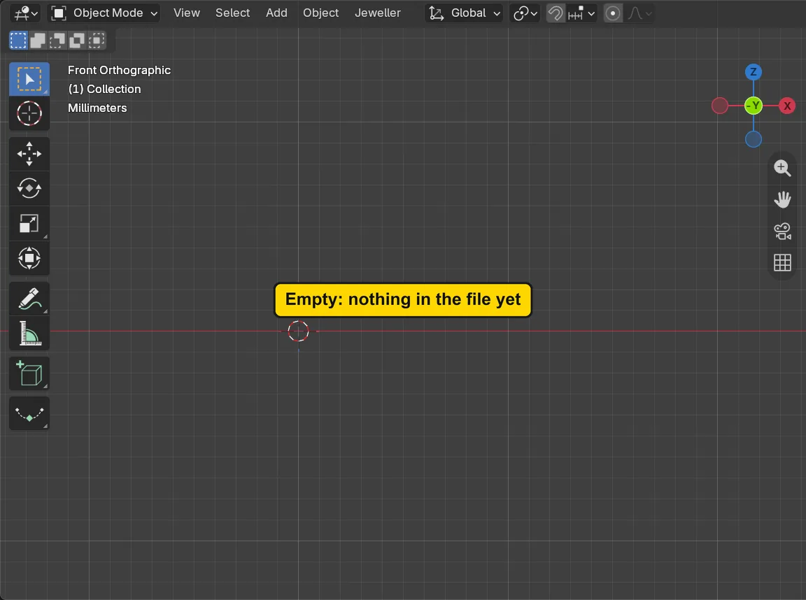
You should seeThe 3D view shows only the grid: nothing is in the file. The words at the top left of the 3D view begin Front Orthographic. The title bar, the strip above File and Edit, begins my-bracelet-section.
It worked whenThe title bar, the strip above File and Edit, begins my-bracelet-section.
Step 2. Change the plane and look from above
WhereThe sidebar: the CAD/CAM tab, then Draw in the section bar. Then the Draw panel, the Next Plane button. Then the header, the row of words along the top of the 3D view: View.
DoClick the CAD/CAM tab, click Draw, press Next Plane twice, then choose View > Viewpoint > Top.
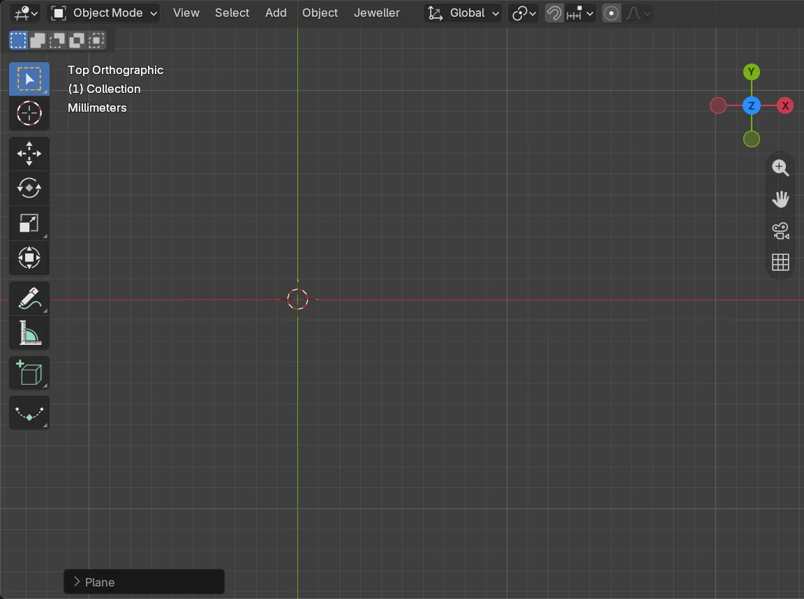
You should seeThe 3D view looking straight down on the grid: the red line is the X axis and the green line is the Y axis. The small box at the bottom left, headed Plane, is Blender’s Adjust Last Operation box: leave it alone. The links lie flat on the Top plane, and you draw them from above.
It worked whenThe words at the top left of the 3D view begin Top Orthographic.
Step 3. Draw the link’s window
WhereThe Draw panel, the Circle button. Then the 3D view: put the pointer on the 3D cursor, the red and white ring at the world origin, where the red and green lines cross.
DoPress Circle, put the pointer on the 3D cursor, type 10x5, then press Enter.
Type10x5
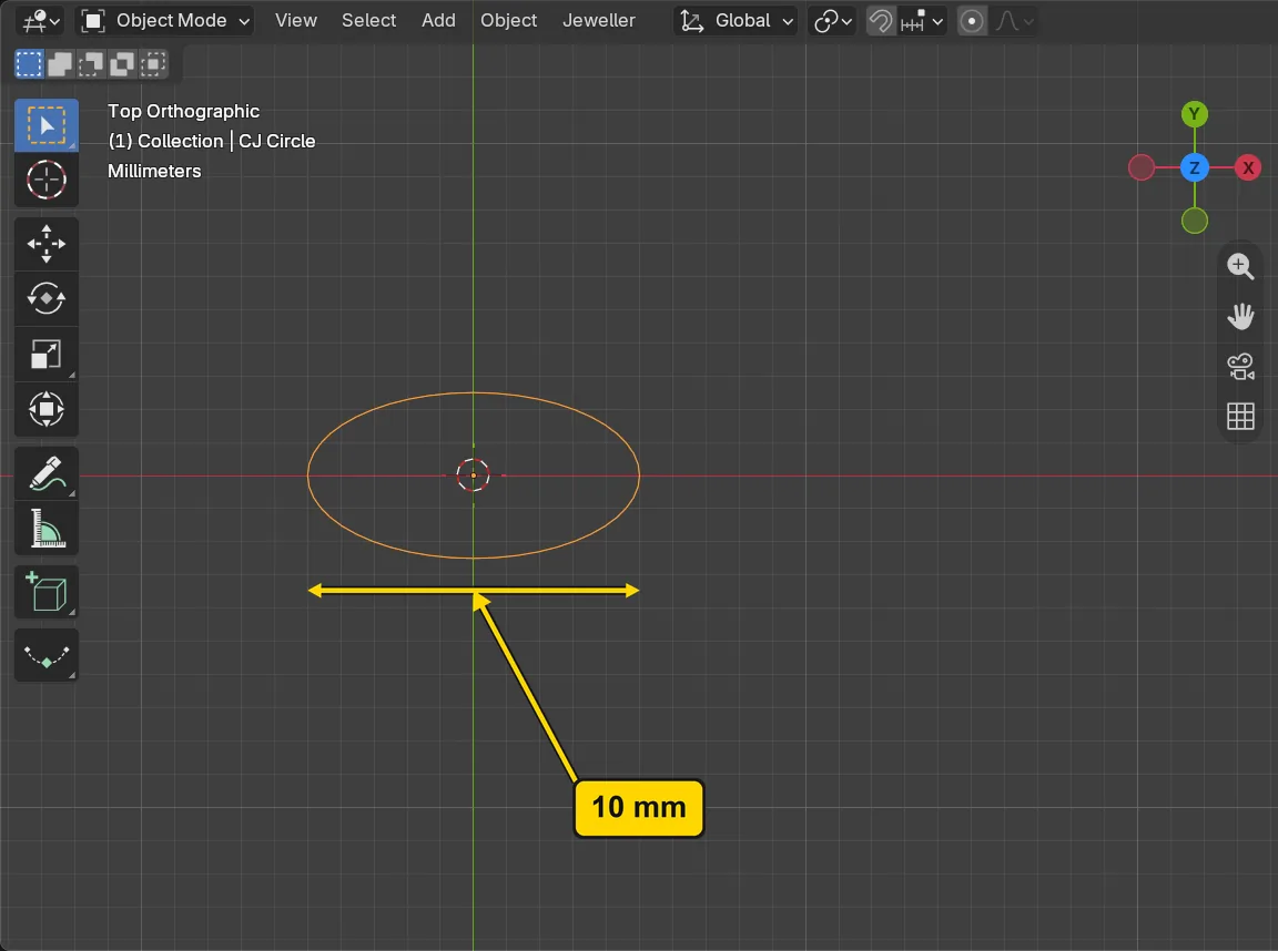
You should seeAn oval 10 mm across and 5 mm up, with its middle on the pointer. On the 3D cursor the line of words under the header reads “Snap: Point” and the oval takes the cursor’s place exactly. The x between the numbers is the letter x: a circle typed as two sizes is an oval. This is the link’s window, the hole through it. The page draws the window first and the outline round it.
It worked whenAn oval stands at the middle of the 3D view.
Step 4. Draw the link’s outline round it
WhereThe Draw panel, the Circle button. Then the 3D view: the pointer on the middle of the small oval.
DoPress Circle, put the pointer on the middle of the small oval, type 14x9, then press Enter.
Type14x9
You should seeA larger oval, 14 mm across and 9 mm up, round the window with the same middle. Near the middle of the small oval the line of words under the header reads “Snap: Point” and the new oval takes that middle exactly. The metal between the two is 2.00 at each end bar and 2.00 at the top and bottom: (14 - 10) / 2 and (9 - 5) / 2. It is thinnest, 1.93, a little way round, because the two ovals are not parallel. All of it is over 0.80, the bench’s number for metal that carries load.
It worked whenA larger oval stands round the smaller one.
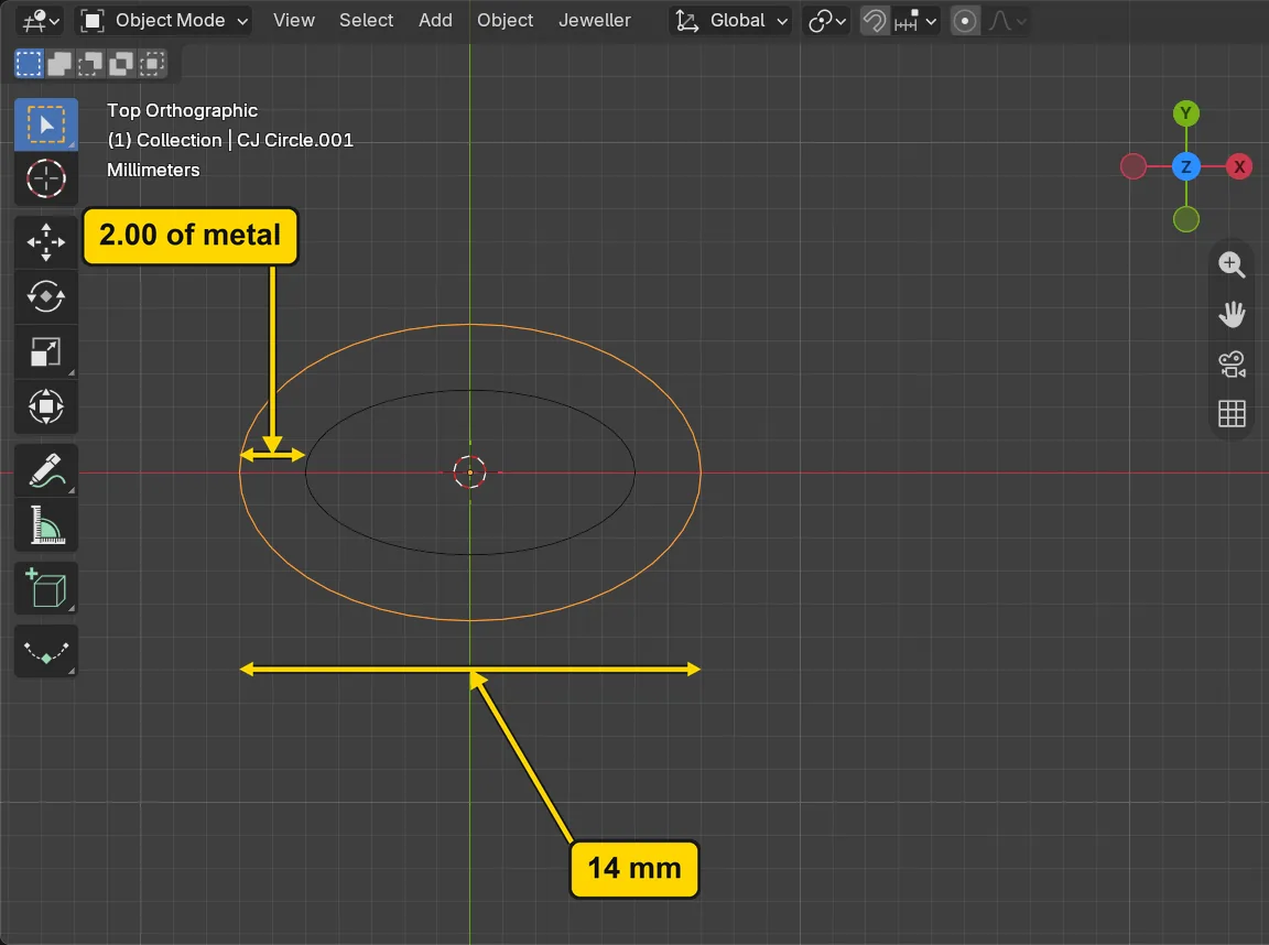
Step 5. Prove the metal at the end bar with the Ruler
WhereThe section bar: Measure. Then the Ruler panel, the Start Ruler button. Then the 3D view: the left-hand end of the two ovals, on the line through their middle.
DoClick Measure in the section bar, press Start Ruler, click the left-hand point of the small oval, click the left-hand point of the large oval, press Esc, read the box under the Ruler buttons, then press Clear All.
You should seeA line between the two points with its length written beside it, 2.01 mm in view, and the same figure in the box under the Ruler buttons. That is the metal at the link’s end bar, between the window and the outline: 2.00 by the sizes of the two ovals, and your click lands near the point, not on it, so your reading may differ by a few hundredths. It is over 0.80, the bench’s number for metal that carries load. Clear All takes the ruler off the screen: you have its number.
It worked whenThe box under the Ruler buttons read 2.01 before you pressed Clear All.
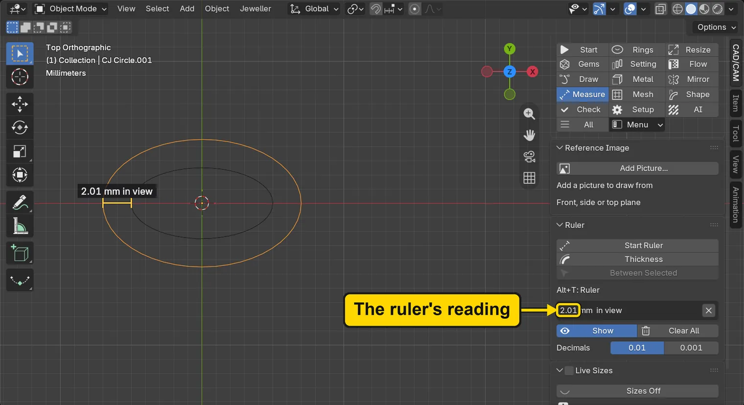
If it goes wrongThe reading is a little more or less than 2.01: A click missed the point and landed beside it. Press Backspace to remove the ruler and click the two points again.
Step 6. Make the outline a plate
WhereThe section bar: Metal. Then the Metal panel: the Make Plate button. The outline is the selected curve.
DoClick Metal, press Make Plate, then type 1.2 in Thickness up (mm), and 0.3 in Round top edge (mm) and in Round bottom edge (mm), each followed by Enter.
You should seeA solid oval plate, and in the panel the name Plate 1 with its numbers. Thickness up (mm) is metal above the plane the oval was drawn on: 1.20 is this exercise’s thickness, over the 0.80 least. Round top edge (mm) and Round bottom edge (mm) soften both edges by 0.30: the top so that the link does not catch a sleeve, the bottom because the bottom edge lies on the skin. The window is not cut yet: the plate is solid.
It worked whenThickness up (mm) reads 1.200, and the two round edges read 0.300.
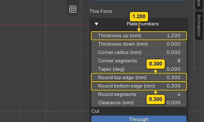
Step 7. Add the window as a cutter
WhereThe Outliner: the row CJ Circle, the window. Then the 3D view: the plate’s metal between the two edges at the left. Then the Live Forms panel: Add Selected, under Cutters.
DoClick CJ Circle in the Outliner, hold Shift and click the plate’s metal at the left, then press Add Selected under Cutters.
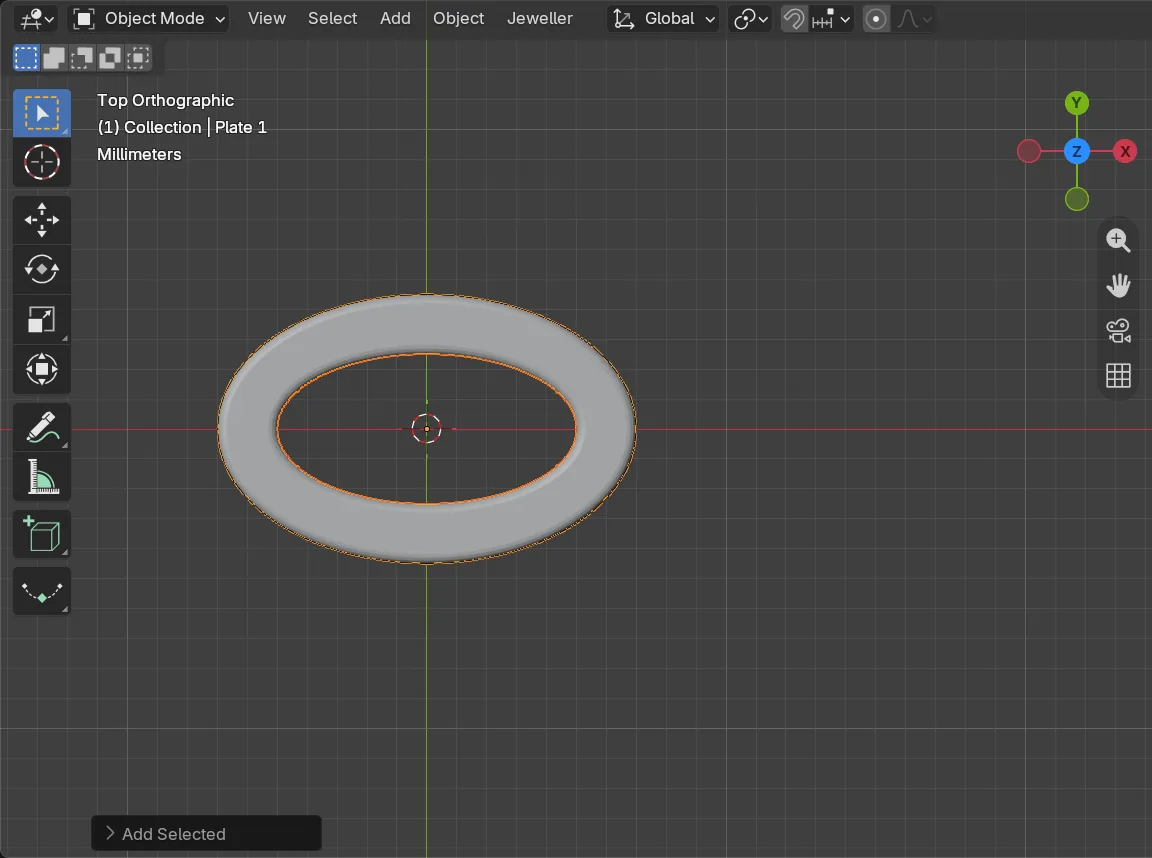
You should seeA window cut through the plate: the 3D view shows a link with a hole. The window stays live: moving or resizing its curve moves or resizes the hole. The plate was the active one, so the window went in as its cutter.
It worked whenThe 3D view shows an oval link with a window through it.
Step 8. Make the link real
WhereThe Live Forms panel: the Make Real button. The plate, Plate 1, is the selected form.
DoPress Make Real.
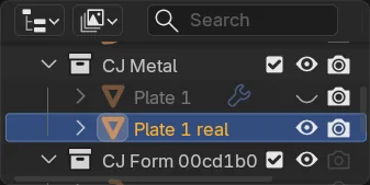
You should seeA new row in the Outliner, Plate 1 real: an ordinary object, the link, the selected one. It no longer follows the drawing. The live plate stays in the list, hidden, in case you want to change a size: a wrench beside a row is Blender’s mark for a modifier, the part that keeps a form live, and a shut eye hides it. The ordinary object can be copied and moved by typed numbers.
It worked whenThe Outliner lists Plate 1 real.
Step 9. Copy the link twice by a typed move
WhereThe 3D view: move the pointer off the sidebar and into the dark area. The link is the selected one.
DoPress Shift+D, X, type 12, then press Enter. Do it again with the new link selected.
Type12
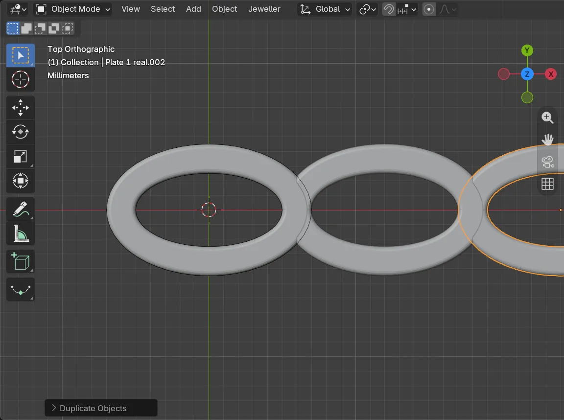
You should seeA second link 12 mm to the right of the first, then a third 12 further on, standing at X 24. Neighbours overlap by 2.00 at their end bars, 14 - 12. Shift+D makes a copy and starts a move, X keeps the move along X, and the number is the distance in millimetres. The copy of a copy is moved 12 from the copy. If the third link is off the screen, press Home with the pointer over the 3D view, or choose View > Frame All.
It worked whenThree links stand in a row, each overlapping the next at one end.
If it goes wrongNothing moves, or a letter shows in a field: The pointer was over the sidebar. Move it over the 3D view and press the keys again.
Step 10. Raise the second link
WhereThe 3D view: the second link, in the middle of the row. Click on its metal at the top of the oval, then keep the pointer in the dark area.
DoClick the second link at the top of its oval, press G, Z, type 1.7, then press Enter.
Type1.7
You should seeThe second link standing 1.70 higher than the first and third. The flat metal is 1.20 thick, so the end bars of neighbours stack with 0.50 between them: 1.70 - 1.20 = 0.50. The links alternate low, high, low, so that each pair of end bars lies one over the other and one ring takes both. From above you cannot see the lift: the next step looks from the front, as the picture does.
It worked whenThe second link stands higher than the others.

Step 11. Look from the front and change the plane
WhereThe header: View. Then the section bar: Draw, and the Draw panel, the Next Plane button.
DoChoose View > Viewpoint > Front, click Draw in the section bar, then press Next Plane twice.
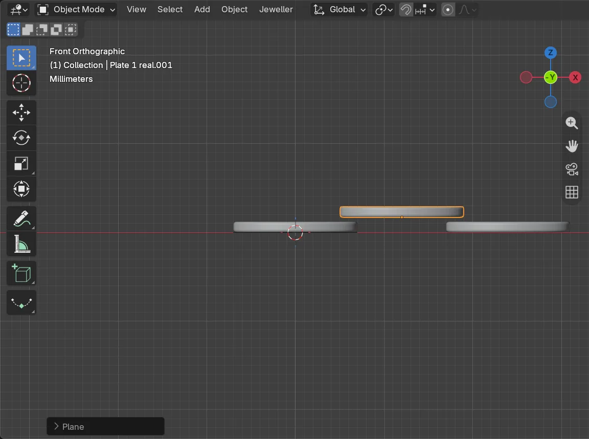
You should seeThe 3D view looking straight at the front: the three links are flat bars, the middle one higher. The plane is now View, the plane that faces you, through the 3D cursor: because you look straight at the front, it is the front plane. The ring is drawn upright on it, so you draw it from here. The small box at the bottom left, headed Plane, is Blender’s Adjust Last Operation box: leave it alone.
It worked whenThe words at the top left of the 3D view begin Front Orthographic.
Step 12. Draw the ring’s circle
WhereThe Draw panel, the Circle button. Then the 3D view: an empty place above the links.
DoPress Circle, put the pointer in the dark area above the links, type d5.2, then press Enter.
Typed5.2
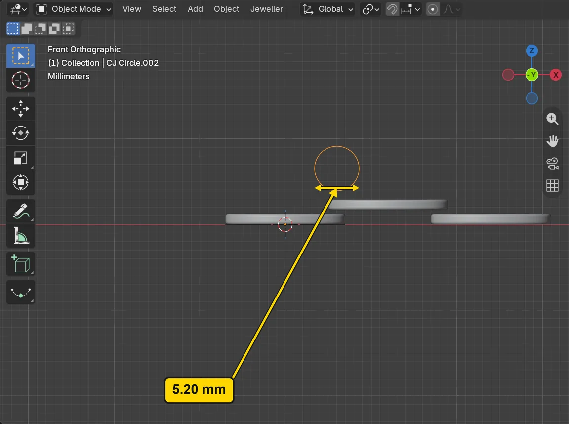
You should seeA circle 5.20 across, standing upright above the links, on the plane that faces you. It is the middle line of the ring: the ring’s wire will be 0.80 thick, so the ring will measure 5.20 + 0.80 = 6.00 across outside and 4.40 inside. Where you draw it does not matter: the ring is placed by typed numbers two steps on. It must stand with its middle at X 6.00 and Z 1.45, because there the end bar of the first link overlaps the end bar of the second, and the ring then runs round both with about 0.4 to spare.
It worked whenA circle stands above the links, and the line of words under the header, which showed while the Circle tool ran, has gone.
Step 13. Make the circle into wire and check it
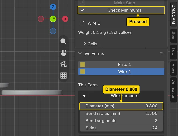
WhereThe section bar: Metal. Then the Metal panel: Make Wire and Check Minimums. Then the Live Forms panel, This Form, the box Wire numbers: the field Diameter (mm).
DoClick Metal, press Make Wire, type 0.8 in Diameter (mm), then press Check Minimums.
You should seeA thin round wire along the circle, 6.00 across outside, and the status bar reading “2 live forms checked: nothing under the minimums” before it fades. Both live forms were checked, the plate and the ring: the thinnest metal is the ring’s wire, 0.80, and the link’s thinnest metal is 1.93. The add-on warns under 0.60. 0.80 is the least for metal that carries load, and a bracelet is the hardest place to use it: a thicker wire would be safer.
It worked whenThe Metal panel shows no warning line under the Weight line.
Step 14. Make the ring real
WhereThe Live Forms panel: the Make Real button. The ring, Wire 1, is the selected form.
DoPress Make Real.
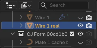
You should seeA new row in the Outliner, Wire 1 real: an ordinary object, the ring, selected. The live wire Wire 1 is kept, hidden, with its wrench and its shut eye. The ordinary object can be moved and copied by typed numbers: the live wire stays where you drew the circle.
It worked whenThe Outliner lists Wire 1 real.
Step 15. Put the ring in its place
WhereThe section bar: Shape, the Centre and Size panel, the Origin to Centre button. Then the Item tab: the X, Y and Z fields under Location:.
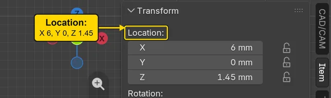
DoPress Origin to Centre, click the Item tab, click the X field under Location:, type 6, press Tab, type 0, press Tab, type 1.45, then press Enter.
You should seeThe ring standing round the two end bars where the links overlap: the low link’s end bar in the lower half of the ring, the high link’s in the upper half. Origin to Centre put the ring’s origin, its small dot, at the middle of the ring, so Location: is the ring’s own middle, and typing 6.00 and 1.45 puts that middle exactly there. The end bars of links 1 and 2 overlap between X 5 and X 7 and the stack is 2.90 tall, so the middle of the stack is X 6.00, Z 1.45. A ring placed by eye, a millimetre off, would touch a bar. Your links may stand a fraction of a millimetre off the world origin where your pointer landed: the spare takes that.
It worked whenLocation: reads X 6, Y 0 and Z 1.45, and the ring stands round the end bars in the 3D view.
Step 16. Copy the ring by a typed move
WhereThe 3D view: move the pointer off the sidebar and into the dark area. The ring, Wire 1 real, is the selected one.
DoPress Shift+D, then X, type 12, then press Enter.
Type12
You should seeA second ring, 12 mm to the right of the first, round the end bars of links 2 and 3: Wire 1 real.001, a separate piece. In the Item tab its Location: reads X 18.00, Y 0.00, Z 1.45.
It worked whenA second ring stands 12 mm to the right of the first.
If it goes wrongNothing moves, or a letter shows in a field: The pointer was over the sidebar. Move it over the 3D view and press the keys again.
Step 17. Cut through a ring to see both bars inside it
WhereThe 3D view. The first ring, looking straight at the front.
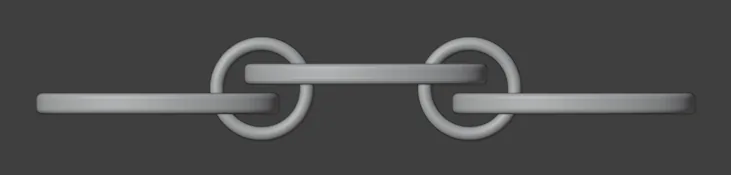
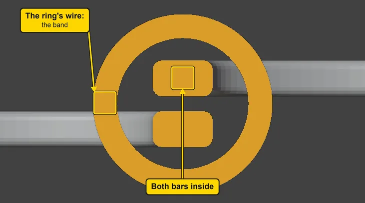
DoLook at the first ring on your screen, then at the picture: a cut along the ring’s own plane, for this picture only. Your file is not cut.
You should seeA cut along the ring, so that its wire shows as an orange band all the way round. Inside it, two bars: the low link’s end bar below and the high link’s above, 0.50 apart, neither touching the band. The ring’s clear radius is 2.20 and the farthest corner of the bars is 1.74 from its middle, so 0.46 stands clear at the nearest corner. The five pieces weigh 3.47 g in 18ct yellow gold.
It worked whenThe picture shows both bars inside the ring’s band, with space round them.
Step 18. Save your work
WhereThe 3D view: move the pointer over it.
DoPress Ctrl+S.
You should seeBlender writes your copy at once, with no question, because the file already has a name. An asterisk, *, in the title bar marks changes that are not saved, and it goes now. Save your work and get it back (P0-12) says more about saving.
It worked whenThe title bar begins my-bracelet-section and carries no asterisk.
No picture: the only change is a message on the status bar, and it fades.
Check your result
| What to read | Where | What it should say |
|---|---|---|
| The link | The Item tab of the sidebar, Dimensions:, with a link selected | X 14.00 mm, Y 9.00 mm, Z 1.20 mm |
| The metal at the link’s end bar | The Item tab, Dimensions:: the outline curve, then the window curve | The outline reads X 14.00 and the window X 10.00: 2.00 mm of metal at each end bar |
| The raised link | The Item tab, Location:, with the middle link selected | X 12.00 mm, Z 1.70 mm |
| The rings’ place | The Item tab, Location:, with each ring selected | The first ring reads X 6.00, Y 0.00, Z 1.45. The second reads X 18.00, Y 0.00, Z 1.45 |
| The fit | The 3D view, looking at the front (View > Viewpoint > Front) | Each ring runs round both end bars with a gap all round: the low bar in the lower half of the ring, the high bar in the upper half, neither touching the wire. Where this page was made the gap at the nearest corner is 0.46 |
| The checks | The Metal panel, with the live plate Plate 1 selected: the lines under its Weight line | None: the thinnest metal of the link is 1.93, over 0.80 |
Try it yourself
Open your copy, click each link in the 3D view and read Location: in the Item tab: the links read X 0.00, 12.00 and 24.00, and the middle one reads Z 1.70. Then click a ring: it reads X 6.00 and Z 1.45, and the copy X 18.00, because the ring’s origin, its small dot, stands at its middle.
What you learned
- A link is an outline made into a plate, with its window added as a cutter, and a jump ring is a circle made into round wire. Make Real turns each into an ordinary object that can be copied and no longer follows its drawing.
- A typed copy is
Shift+D, the axis letter, a number andEnter: the copy lands at exactly that place. Where one piece must pass round another, draw the first, then type the place of the second: the ring’s middle, X 6.00 and Z 1.45, is the overlap of two end bars. - Neighbouring links alternate low and high so that their end bars stack. A cut through a ring shows both bars inside it, with clear space round them.