
What you will make
A north-south oval solitaire in 18ct yellow gold: the oval lies with its long side along the finger, across the width of the band (an east-west oval would lie the other way, across the finger). The panel’s Size reads UK M, 16.70 mm inside; sizing charts differ by about half a size, so check against your own ring sizer. The band is a D Shape 2.2 mm wide and 1.8 mm thick at the sizing area, the part a jeweller cuts and joins to change the size. It thickens to 6 wide and 3.4 thick under the head. An Oval 8 x 6 is an oval stone 8 mm by 6 mm. The head has 4 claws standing 2.00 mm above the table, the stone’s flat top, one thickness from foot to tip, and a second rail under the first. Seen from above, only the stone and its claws show. The add-on weighs the ring at 10.03 g in 18ct yellow gold (0.57 g of head and 9.46 g of band): that is heavy for a solitaire, because this ring is a drill in the tools, not a design to cast. The ring goes out in both forms: one fused body for the prototype print, and a head and a shank apart for production. Three STL files are written, named by use, once all three bodies pass the print check. They are practice files: do not send them to anyone.
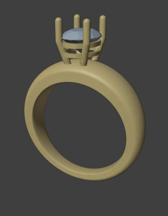
About 30 minutes.
Files
- p4-11-start.blend (98 KB): open this one to begin.
- p4-11-finished.blend (10.54 MB): the result, to compare with yours.
Both were made in Blender 5.2.0.
Before you start
- CAD/CAM Jeweller 2.22.0 or later (Preferences > Add-ons shows the version). You have done Part 0, Blender from nothing, Build a band to a ring size (P1-01), Make a head real, alone and as a prototype (P4-09) and Part a ring into head and shank (P4-10). Steps 8 and 9 are P4-09’s steps 4 to 9 again, in short: keep that page open beside this one. The start file is an empty file in millimetres.
- You choose a stocked size, a size a dealer sells as a calibrated stone: here an Oval 8 x 6. The claws stand 2.00 mm above the table and keep one thickness, and no rail shows from above: those are the add-on’s starting numbers, and you do not change them.
Build it
Step 1. Open the start file and save your copy
WhereThe top bar: the row of words that begins File, Edit.
DoDownload p4-11-start.blend from Files above and open it. Then choose File > Save As and save it under the name below, in a folder of yours. Open an exercise file and keep the start file safe (P0-07) shows how.
Typemy-oval-solitaire.blend
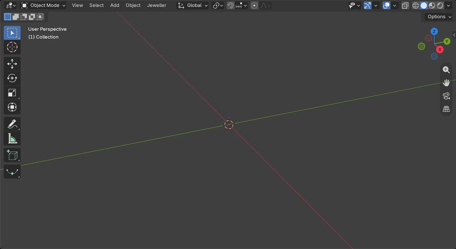
You should seeThe 3D view is empty: no band, no stone. The title bar, the strip above File and Edit, begins my-oval-solitaire.
It worked whenThe title bar, the strip above File and Edit, begins my-oval-solitaire.
Step 2. Set the top of the band
WhereThe sidebar: the CAD/CAM tab, the section bar, Rings, then the Rings panel, the one of Build a band to a ring size (P1-01). If the sidebar is shut, press N with the pointer over the 3D view.
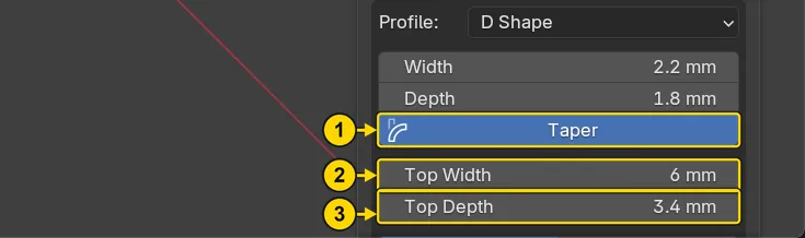
DoClick Taper, then click the middle of Top Width, type the number and press Enter. Do Top Depth the same way.
You should seeTaper is lit and the fields read the table. The panel starts at UK and M, a ring size, with Profile D Shape, Width 2.2 and Depth 1.8: that is the back of the band, the sizing area. Taper makes the band thicker under the head.
| Field | Type | It then reads |
|---|---|---|
| Top Width | 6 | 6 mm |
| Top Depth | 3.4 | 3.4 mm |
| It worked when: Top Width reads 6 mm and Top Depth reads 3.4 mm. |
Step 3. Press Build Shank
WhereThe Rings panel, the button Build Shank.
DoPress Build Shank.
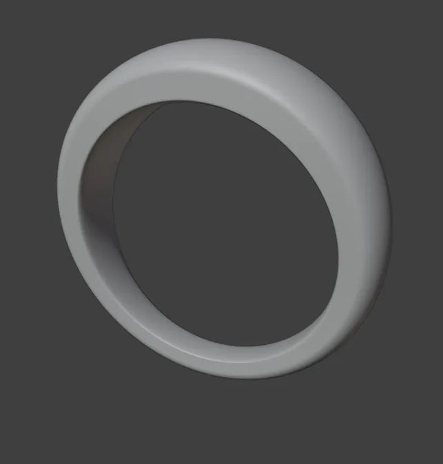
You should seeA band in the 3D view, a ring 16.70 mm inside, thick at the top of the ring, where the head goes, and thinner at the back. The panel’s Size reads UK M, 16.70 mm inside; sizing charts differ by about half a size, so check against your own ring sizer. A ring’s inside is its bore.
It worked whenA band stands in the 3D view.
Step 4. Choose an Oval 8 x 6
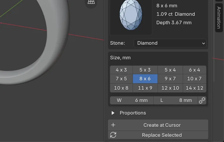
WhereThe section bar, Gems, then the Gems panel: the picture of the stone, then the Size, mm box.
DoClick the picture, click Oval in the grid that opens, then click the chip 8 x 6.
You should seeThe lines beside the picture read Oval and 8 x 6 mm. A chip is a stocked size. Nothing is made yet.
It worked whenThe lines beside the picture read Oval and 8 x 6 mm.
Step 5. Make the stone at the cursor
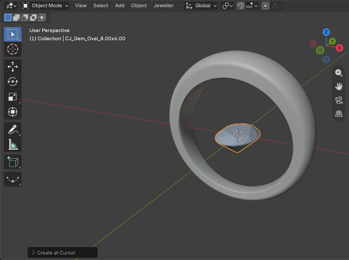
WhereThe Gems panel, the button Create at Cursor.
DoPress Create at Cursor.
You should seeA pale oval stone in the middle of the ring’s hole, at the 3D cursor, the red and white ring where the world’s lines cross. The next step lifts it onto the band.
It worked whenThe words at the top left of the 3D view name CJ_Gem_Oval_8.00x6.00.
Step 6. Lift the stone onto the band
WhereThe 3D view: move the pointer off the sidebar and into the dark area. The stone is selected.
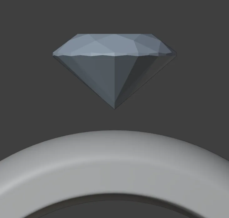
DoPress G, then Z, type 15.425 and press Enter.
You should seeThe stone moves straight up and stands just over the top of the band. G starts a move, Z keeps it to the up-and-down line, and the typed number is how far it goes, in millimetres. The sum: the band’s top is at 11.75 (half the inside, 8.35, and the Top Depth, 3.4), and the stone’s middle stands 3.675 over it, so 15.425 is 11.75 and 3.675 together. 3.675 is the figure this oval’s head needs: step 7 shows where it comes from. On another band, the stone’s height is that band’s top plus 3.675. The oval lies north-south: its long side runs along the finger, across the band’s width, and the picture is from the front. With the long side round the finger instead, the claw feet would stand about 0.5 mm clear of the band’s curve, further than the 0.40 mm that Prototype runs them in.
It worked whenThe stone stands just over the top of the band, in the middle of its thick top.
If it goes wrongNothing moves and the keys type nowhere: the pointer is still over the sidebar. Move it over the 3D view and press the keys again.
If it goes wrongPrototype says “Head with shank is not the body” at step 8, and every face of the band is a triangle: the stone’s height is wrong. Click CJ_Gem_Oval_8.00x6.00 in the Outliner (the list at the top right), click the Item tab (the tab at the sidebar’s edge, below CAD/CAM) and type 15.425 in the Z of Location.
Step 7. Press Make 1 Head
WhereThe section bar, Setting, then the Head Builder panel, the button Make 1 Head.
DoClick Setting, leave every number as it is, and press Make 1 Head.
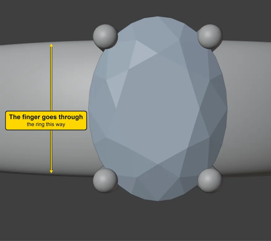
You should seeFour claws round the oval, a pair at each end of its long side, 35 degrees either side of the long axis. Claw reads 1.1 mm and Over the table reads 2 mm. The add-on gives a claw 0.18 of the stone’s width, in steps of 0.05, never under 0.60: the oval’s narrow side is 6.00, so 1.08 becomes 1.1, and a Round 6.50 gets 1.15. A second rail stands under the first, and both are under the stone: from above only the stone and its claws show. The picture is from straight above. The double arrow is the line of the finger: it goes through the ring along the band’s width, so the oval lies along it, north-south, and the band runs across the picture. The panel’s own sentence reads that the foot plane stands 3.54 under the girdle’s lower edge. That is where step 6’s 3.675 comes from: the foot plane stands 3.625 under the stone’s middle, and it is to stand 0.05 over the band’s top, so the stone’s middle must stand 3.625 and 0.05, together 3.675, over the band’s top.
It worked whenOver the table reads 2 mm.
Step 8. Make the ring in both forms, as in P4-09
WhereThe same places as Make a head real, alone and as a prototype (P4-09), steps 4 to 9: the section bar’s Metal, the 3D view, Setting and Check. Keep that page open beside this one.
DoDo the five moves of the list below, one after the other. Each is a step of P4-09 that you have done, with this band, CJ_Shank_DShape_M, and this head.
You should seeThe five moves, each with the P4-09 step that teaches it, and what shows when it has worked:
- Metal, Live Forms: click the band’s row, CJ_Shank_DShape_M, then press Make Real under This Form (P4-09 step 4). The row leaves the list.
- In the 3D view:
Tab,A, Face > Triangulate Faces,Tab(P4-09 steps 5 and 6). The words at the top left of the 3D view say Object Mode again. - Hold
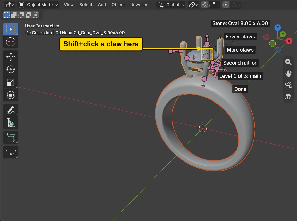
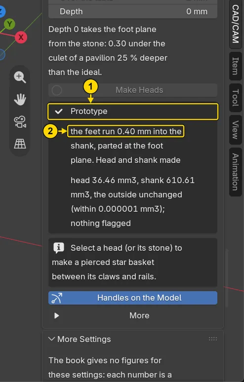
Shiftand click a claw, at the point in the picture (P4-09 step 7). The band is still selected from move 2; if it is not outlined, click the band first. The words at the top left of the 3D view name the head, and the band is outlined too. A click on a claw selects the head; a click on the stone would select the stone alone. - Setting, then Prototype (P4-09 step 8). The grey box reads “Prototype: the feet run 0.40 mm into the shank, parted at the foot plane”, then head 36.46 mm3, shank 610.61 mm3 and “nothing flagged”. In the picture, the words marked 2 are the start of that sentence. “Nothing flagged” is not a check of the joint: Measure Parting (P4-10) at the foot plane, 11.80, reads Least metal at the joint head 0.84 and shank 0.40. The shank’s figure is under the 0.60 least for structural metal, and the add-on does not flag it. Its 0.40 is the claw feet’s root in the shank: a practice joint.
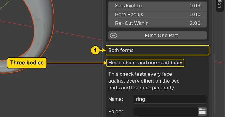
- Check, Reports & Checks, Head and Shank (P4-09 step 9). The box Both forms reads “Head, shank and one-part body”. It worked when: The box Both forms reads “Head, shank and one-part body”.
If it goes wrongPrototype says “Select a shank with the head for the prototype” with the band selected: the band is still live. Do move 1 first, then select the band and the head again and press Prototype.
If it goes wrongPrototype says “Head with shank is not the body”: the band still has four-sided faces (do move 2 again), or the stone’s height is wrong: click CJ_Gem_Oval_8.00x6.00 in the Outliner, click the Item tab and type 15.425 in the Z of Location.
Step 9. Run Print Check Parts, then Export Both Forms
WhereThe box Both forms: the buttons Print Check Parts and Export Both Forms.
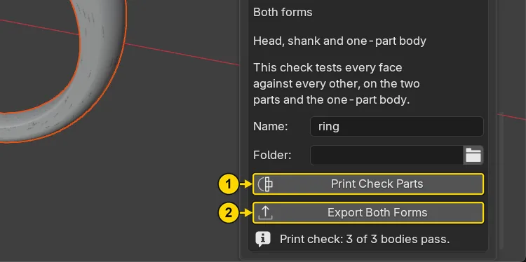
DoPress Print Check Parts, read its sentence, then press Export Both Forms. Wait for the files.
You should see“Print check: 3 of 3 bodies pass.” and then, under the export, “Both forms written to” and your folder. The files stand beside your saved copy: one_part_prototype holds ring_one_part_mm.stl, and two_parts_production holds ring_head_mm.stl and ring_shank_mm.stl. “3 of 3 bodies pass” says that each body is closed and sound to print: it says nothing about strength or fit. No file is written unless all three bodies pass. The notes file that goes with them, ring_parts_notes.txt, gives the ring’s weight: “One part: 647.0733 mm3, 10.03 g in 18ct yellow (as modelled, before sprue, polish and setting)”, the head 0.57 g and the shank 9.46 g. 10.03 g is heavy for a solitaire: the band is 9.46 g of it, and the taper under the head adds to that. This ring is a drill in the tools: a real job would be weighed, and the band slimmed, before it was cast.
It worked whenThe box under Export Both Forms begins “Both forms written to”.
Step 10. Save your work
WhereThe 3D view: move the pointer over it.
DoPress Ctrl+S.
You should seeBlender writes your copy at once, with no question, because the file already has a name. An asterisk, *, in the title bar marks changes that are not saved, and it goes now. Save your work and get it back (P0-12) says more about saving.
It worked whenThe title bar begins my-oval-solitaire and carries no asterisk.
No picture: the only change is a message on the status bar, and it fades.
Check your result
| What to read | Where | What it should say |
|---|---|---|
| The head | The CAD/CAM tab, Setting section, Head Builder panel, the numbers under the two pictures | Claw reads 1.1 mm and Over the table reads 2 mm |
| The prototype’s sentence | The Setting section, Head Builder panel, the grey box under Make Real and Prototype, as it stood at step 8 | It begins “Prototype: the feet run 0.40 mm into the shank” and reads head 36.46 mm3, shank 610.61 mm3 |
| The three bodies | The Check section, Reports & Checks, Head and Shank, the box Both forms | The line under Both forms reads “Head, shank and one-part body” |
| The sentence of the last button | The same box, under Export Both Forms | It begins “Both forms written to” and ends “4 files, each read back.” |
| The files | The folder of your saved file, in your computer’s own file manager | one_part_prototype holds ring_one_part_mm.stl, and two_parts_production holds ring_head_mm.stl and ring_shank_mm.stl |
| The ring’s weight | The notes file beside them, ring_parts_notes.txt, opened in any text editor | “One part: 647.0733 mm3, 10.03 g in 18ct yellow”, the head 0.57 g and the shank 9.46 g |
| The joint | The Head and Shank panel after Measure Parting (P4-10), at the foot plane | Least metal at the joint: head 0.84, shank 0.40. The shank’s figure is under the 0.60 least: a practice joint |
Try it yourself
Open your copy again and press Print Check Parts once more: the box under Both forms reads “Print check: 3 of 3 bodies pass.” Then open ring_parts_notes.txt and check that the head’s 0.57 g and the shank’s 9.46 g add to the one part’s 10.03 g. These are practice files: take them no further.
What you learned
- A solitaire joins the band, the stone, the head and both forms: every step before is one of those tools, pressed in order.
- Prototype needs an ordinary band made of triangles and a stone set so that the head’s foot plane stands just over the band’s crest: the stone’s middle stands 3.675 mm over the crest here, typed as its height (the band’s top 11.75 and 3.675 make 15.425).
- Print Check Parts says each body is closed and sound to print, and Export Both Forms writes the three files only when all three pass. That says nothing about strength or fit: these are practice files, and a real job is sent only after your caster and setter have seen the joint.