

The Draw section is where a piece starts as a line: you draw a curve at true size on a plane, with exact lengths and angles. The Metal section then turns the curve into wire, strip or plate that stays joined to the drawing, so when you move a point the metal follows. Reach for them for pierced plates, wire work, galleries and anything that starts as an outline.
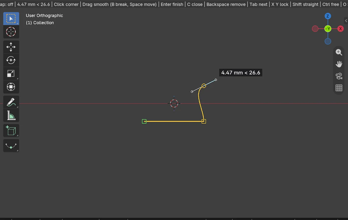
Where to find it
CAD/CAM tab > Draw section for the pen, the shapes, the planes, the snaps and the guides. CAD/CAM tab > Metal section for the Make buttons and the Live Forms list. Keys: Shift+Q starts the pen and Shift+J opens the Draw and Metal pie. Menu: Jeweller > Metal.
Use it
Step 1. Draw an outline
WhereCAD/CAM tab > Draw section > Draw panel.
Doclick Pen (Shift+Q), then click each corner in the 3D view. Drag instead of clicking for a smooth point. To make a side exact, type its length, press Tab, type its angle and press Enter: 12, Tab, 45, Enter. Press C to close the outline.
You should seea curve object, and what you have typed in the header. Esc cancels a drawing in progress, and the first Esc only clears the numbers you typed.
Step 2. Add a hole
Wherethe Draw panel.
Doclick Circle, press at the centre and drag out to the radius. Or type r4 and press Enter for a radius of 4 mm.
You should seea second closed curve.
Step 3. Make the plate
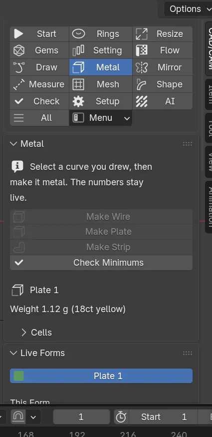
WhereCAD/CAM tab > Metal section > Metal panel.
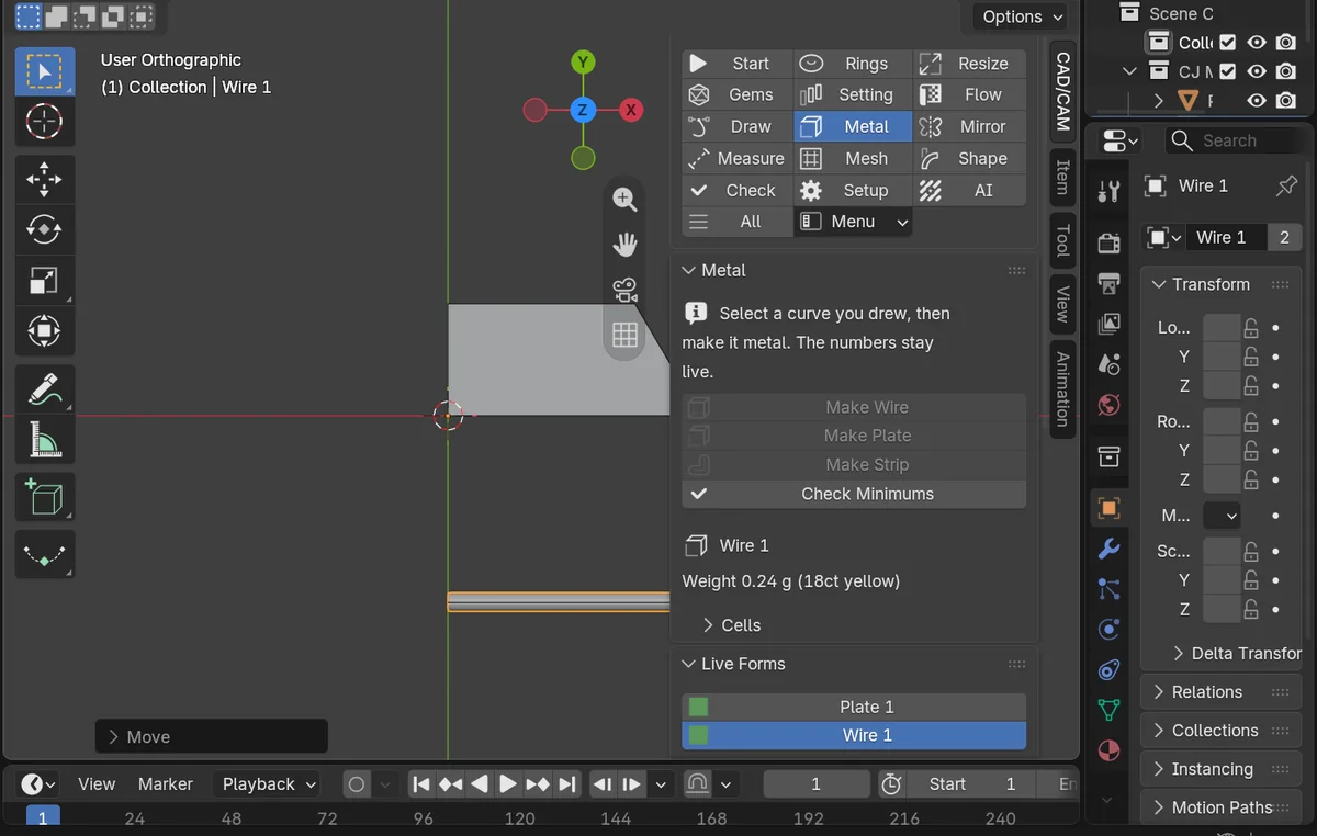
Doselect the outline, then click Make Plate. For a wire along an open curve click Make Wire, and for a flat strip click Make Strip.
You should seethe solid, with a state dot beside it in the Live Forms list and its weight in the alloy chosen in Setup.
If it goes wrongthe buttons are greyed until a curve is selected. A wire bend sharper than the wire allows is refused.
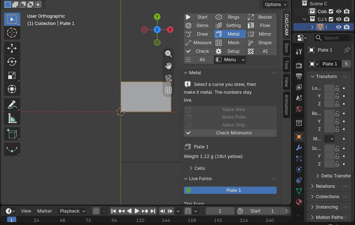
Step 4. Cut the hole
Wherethe Live Forms list, under This Form > Sources.
Doselect the circle, then click Add Selected beside Cutters.
You should seea hole in the plate that moves with the circle.
Step 5. Move a point
Whereunder This Form > Sources.
Doclick Select beside the outline, press Tab, select a point and press G.
You should seethe plate rebuild as you drag. A light form follows the pointer. A heavy one waits for the mouse to rest, or for Rebuild.
Step 6. Make it real
WhereLive Forms > This Form.
Doclick Make Real.
You should seethe form baked into a plain mesh. The sources stay, so it can be made real again.
The Draw tools
| Button | What it does |
|---|---|
| Pen (Shift+Q) | Click for a corner, drag for a smooth point, type a length and an angle for an exact side. |
| Edit Points | Moves a point, a handle or a segment of the active drawing. B breaks a handle, A rejoins it, Ctrl+click inserts a point. |
| Rectangle | Drag, or type a size such as 20x10. |
| Circle | Drag, or type r4, d8 or 8x5 (an ellipse). |
| Polygon | Drag to a corner. The wheel or n6 sets the sides. |
Plane, Next Plane (P) | Chooses the plane the drawing sits on. |
Add Guide (L), Clear Guides | Construction lines that the snaps use. |
Planes. The pen draws on a plane, so a length you type in millimetres is a length on the piece: Front, Side, Top, Ring (select the ring first), Face (press F in the pen, then click a face), Flow Guide, Picture (a reference picture) or View. Origin At says where Front, Side and Top sit: World, 3D Cursor or Last Point.
Typing. 12<45 is 12 mm at 45 degrees. 3,4 is 3 across and 4 up from the last point. #3,4 is the same from the plane’s origin. Tab moves to the next field.
Snaps. Twelve kinds, each with its own switch: End, Mid, Centre, Crossing, Square, Tangent, Quarter, Nearest, Point, Track, Grid and Stone. The label beside the pointer names what it found, for example Stone centre, Girdle or Seat. Tab cycles the candidates. Holding Ctrl switches the snaps off. Polar Step (15 degrees by default) snaps a direction to multiples of the step when it is within 2 degrees. Resting the pointer for 0.4 second on a point tracks it.
Mirror. Across Y or Across X draws both sides at once and closes the outline as one shape. Keep Symmetrical holds it so when you edit the points afterwards.
Settings
Wire.
| Setting | Default | What it changes |
|---|---|---|
| Diameter | 1.00 mm | The thickness of the round wire. 0.10 to 12 mm. |
| Bend radius | 1.50 mm | Held at 1.05 times the wire radius at least. A sharper bend is refused. |
| Sides | 24 | The smoothness of the round section. 8 to 64. |
Strip.
| Setting | Default | What it changes |
|---|---|---|
| Width | 1.50 mm | Across the path. 0.30 to 30 mm. |
| Side | Centre | Which side of the path the width sits on: Centre, Left or Right. |
| Join | Round | How a bend is closed on its outer side: Mitre, Round or Chamfer. |
| Ends | Flat | An open path ends cut off, extended by half the width (Square), or in a half circle (Round). |
Plate.
| Setting | Default | What it changes |
|---|---|---|
| Thickness up | 1.00 mm | Metal above the sketch plane. 0 to 20 mm. |
| Thickness down | 0.00 mm | Metal below the sketch plane. |
| Corner radius | 0.00 mm | Rounds every corner of the outline. |
| Taper | 0 degrees | Slopes the walls. -30 to 30 degrees. |
| Round top edge, Round bottom edge | 0.00 mm | Rounds the upper or the lower edge. |
| Clearance | 0.00 mm | A cutter’s hole is the cutter grown by this. |
| Cut, Cut depth | Through, 0.50 mm | A hole right through, or a pocket from the top or the bottom. |
| Combine | Union | Several outlines: one plate (Union), or keep and drop the cells they cut each other into (Cells). |
Good to know
- A Live Form keeps its sources. Its state dot reads live (up to date), stale (waiting to rebuild), frozen (too heavy to follow while you drag: press Rebuild) or error (the last rebuild failed, the previous result stays and the findings say why).
- Remove Live keeps the mesh as it is and stops it following its sources. Duplicate makes a copy with its own sources. Clean Up removes the hidden helpers of forms that are gone.
- Save the file and open it again: every form is live again. A form whose sources changed while the file was closed is marked stale and rebuilt.
- Combine: Cells lets you drop regions: select the plate and click Edit Cells, click a cell to drop it or keep it, and press
Enter. A dropped cell follows its shape. - Every form shows its weight and its findings worst first. Each finding says where its figure comes from: the book’s page or a marked house default. Check Minimums runs them again.
- Set Thickness for Weight in the Draw panel and the header shows about what an outline would weigh while you draw.
- Falloff and Hollow Out refuse a live form. Make it real first.