
What you will make
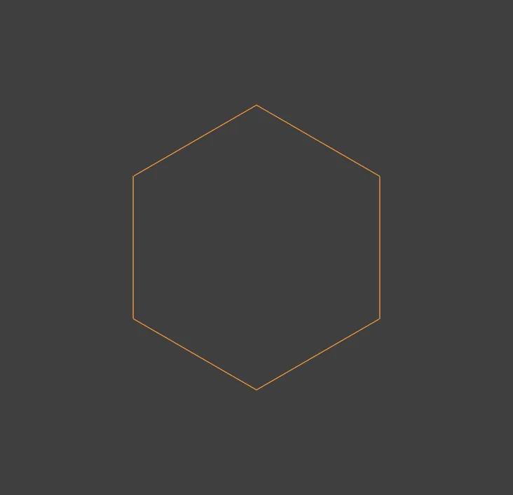
A hexagon 8.00 mm across the flats, drawn on the point where two construction lines cross, with no construction line left in the file. A hexagon is the shape of a nut. Across the flats is the width between two parallel sides, the width a spanner takes. Across the corners, 9.24 mm, is wider. 8.00 across the flats is also the largest hexagon stone made: the outline of a setting for it would be larger.
About 10 minutes.
Files
- p2-04-start.blend (98 KB): open this one to begin.
- p2-04-finished.blend (104 KB): the result, to compare with yours.
Both were made in Blender 5.2.0.
Before you start
- You have done Draw a rectangle and a circle to exact sizes (P2-01): you know the Draw section and that a drawing tool runs until you press
Enter. - The add-on is installed. The start file is empty, in millimetres, and looks straight at the front.
Build it
Step 1. Open the start file and save your copy
WhereThe top bar: the row of words that begins File, Edit.
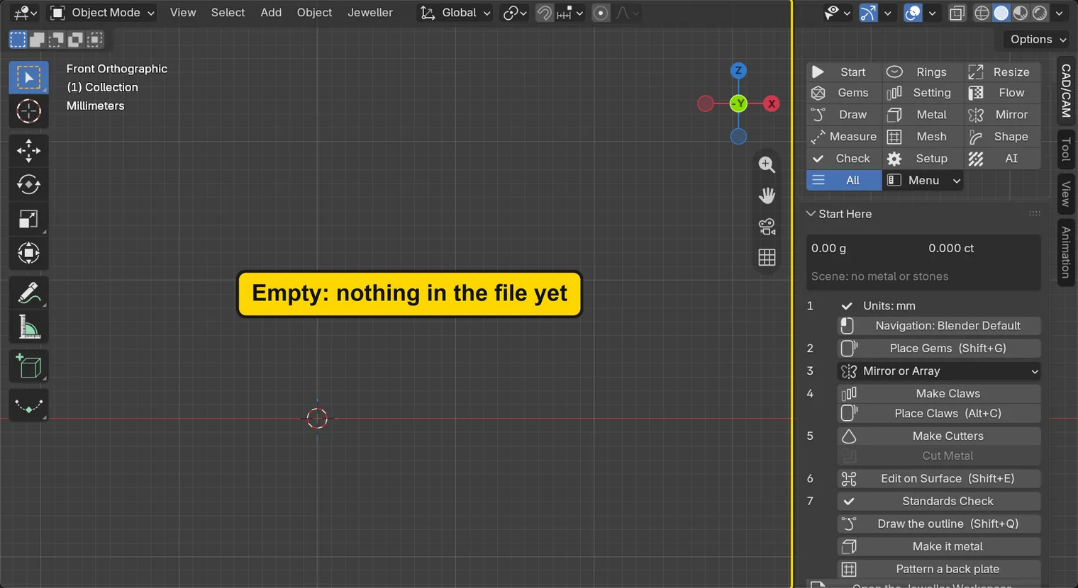
DoDownload p2-04-start.blend from Files above and open it. Then choose File > Save As and save it under the name below, in a folder of yours. Open an exercise file and keep the start file safe (P0-07) shows how.
Typemy-hexagon.blend
You should seeThe 3D view shows only the grid: nothing is in the file. The words at the top left of the 3D view begin Front Orthographic, so the view looks straight at the front.
It worked whenThe title bar, the strip above File and Edit, begins my-hexagon.
Step 2. Open the Draw section and press Add
WhereThe sidebar: the CAD/CAM tab, then Draw in the section bar. Scroll the sidebar down (turn the mouse wheel, or slide two fingers on the touchpad) to the box headed Guides, near the foot of the panel.
DoClick the CAD/CAM tab, click Draw in the section bar, scroll down to Guides, and press Add. Nothing is drawn yet.
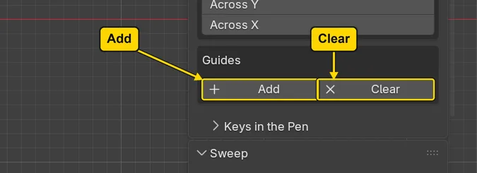
You should seeThe tool’s line, the line of words just under the header, which begins “Pen”: a guide is laid with the Pen. A guide is a construction line: a long thin line that marks a place and is no part of the piece. The status bar, the line along the very bottom of the window, begins “Pen: Guide: click a direction, or type an angle”. The box headed Guides has two buttons, Add and Clear.
It worked whenThe box headed Guides shows Add and Clear, and the tool’s line stands under the header.
Step 3. Lay the first guide
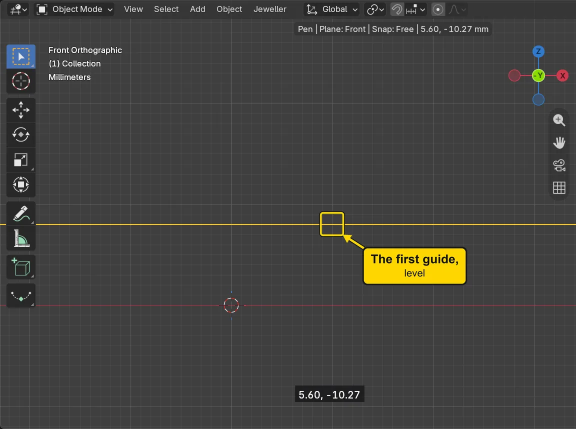
WhereThe 3D view: the middle of the hexagon will stand 10 mm to the right of the 3D cursor and 8 mm above the red line. Each small square of the grid is 1 mm.
DoClick there, then type <0 (hold Shift and press the comma key, the one with < above it on a UK keyboard) and press Enter.
Type<0, then Enter
You should seeA thin line running right across the 3D view through the point you clicked. The first click is a point the line passes through; <0 is its angle: < then the angle, 0 degrees, which is level. A level line is horizontal.
It worked whenA thin horizontal line crosses the 3D view at the height you clicked.
Step 4. Lay the second guide and end Add
WhereThe 3D view: the same point.
DoClick the same point again, type <90 (Shift and the comma key again), press Enter, then press Enter once more to end Add.
Type<90, then Enter, then Enter
You should seeA second thin line, running straight up and down through the same point. 90 degrees is upright. The two lines cross at the middle of the hexagon to come. The second Enter ends the tool; the lines stay.
It worked whenTwo thin lines cross at the point, and the tool’s line is gone.
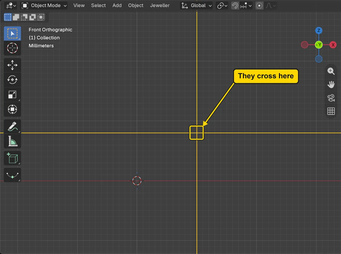
If it goes wrongThe second click lands a little off the first line: Click on the line itself: the click is taken to the line’s middle, which is the first point. If it still misses, press Esc, press Clear, and start the guides again.
Step 5. Press Polygon
WhereThe Draw panel, the Polygon button: scroll the sidebar back up to it.
DoPress Polygon. Nothing is drawn yet.
You should seeThe tool’s line under the header. The Polygon draws a regular shape: all its sides and angles the same. It runs until the hexagon is drawn, and then the tool’s line goes back to the header’s small buttons.
It worked whenThe tool’s line stands under the header.
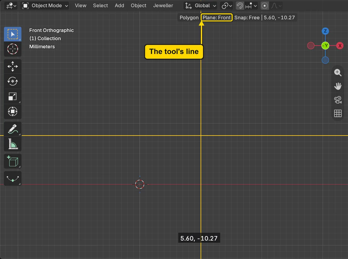
Step 6. Type the sides and the size
WhereThe 3D view: put the pointer on the point where the two lines cross.
DoPut the pointer on the crossing, type n6 and press Enter, then type a4 and press Enter.
Typen6, then Enter, then a4, then Enter
You should seeA hexagon with its middle on the crossing. n6 is six sides; a4 is the distance from the middle to the middle of a flat side, 4 mm, so the hexagon is 8 mm across the flats, with a flat side at the left and at the right and a corner at the top and at the bottom. The pointer is taken to the crossing when it is near, because a snap finds the point where the two lines cross, so the middle of the hexagon lands on it exactly.
It worked whenA hexagon stands on the crossing, with a flat side at the left and at the right.
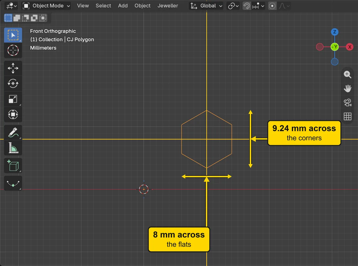
If it goes wrongThe hexagon is not centred on the crossing: The pointer was not on it when you pressed Enter. Press Ctrl+Z, press Polygon again and put the pointer on the crossing first.
Step 7. Read the hexagon’s size in the Item tab
WhereThe sidebar: click the Item tab, the strip of tabs at the right edge of the sidebar, below CAD/CAM.
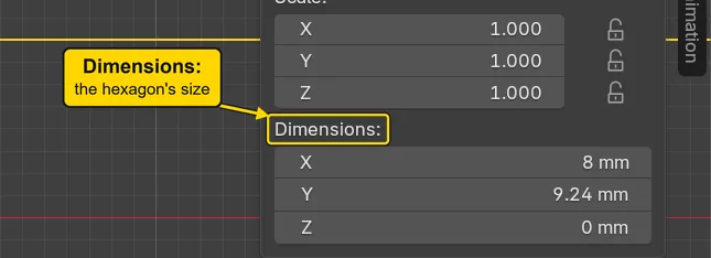
DoClick the Item tab and read Dimensions:. Then click the CAD/CAM tab to come back.
You should seeDimensions: reads X 8.00 mm, Y 9.24 mm, Z 0 mm. X, the width across the flats, is the 8 you set. Y is the width across the corners, wider because a corner sticks out further than a flat.
It worked whenDimensions: reads X 8.00 mm and Y 9.24 mm.
Step 8. Press Clear to take the construction lines away
WhereThe Guides box of the Draw panel: scroll the sidebar down to it.
DoPress Clear.
You should seeBoth thin lines gone from the 3D view, and the hexagon left on its own. Clear takes away every construction line at once. The hexagon is a drawing and stays.
It worked whenOnly the hexagon is left in the 3D view.
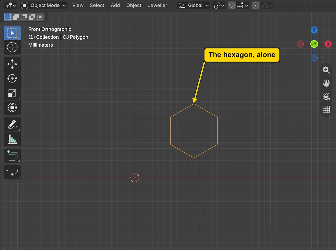
Step 9. Save your work
WhereThe 3D view: move the pointer over it.
DoPress Ctrl+S.
You should seeBlender writes your copy at once, with no question, because the file already has a name. An asterisk, *, in the title bar marks changes that are not saved, and it goes now. Save your work and get it back (P0-12) says more about saving.
It worked whenThe title bar begins my-hexagon and carries no asterisk.
No picture: the only change is a message on the status bar, and it fades.
Check your result
| What to read | Where | What it should say |
|---|---|---|
| The hexagon’s size | The Item tab of the sidebar, under Dimensions: | X 8.00 mm across the flats, Y 9.24 mm across the corners, Z 0 mm |
| The construction lines | The 3D view | No long thin line crosses it: only the hexagon is left |
| The drawing’s name | The words at the top left of the 3D view | They end with CJ Polygon |
Try it yourself
Open your copy again, go to the Draw section and press Polygon. Put the pointer on the 3D cursor, type n8, press Enter, then type r5 and press Enter: an octagon with its corners 5 mm from its middle. Press Ctrl+Z to take it back.
What you learned
- A construction line is a guide, not a part: Add lays one through a point at an angle you type, and the snaps use it. Clear takes every one away.
- Polygon:
n6sets six sides,a4sets the distance from the middle to a flat, andEnterdraws it.rmeasures to the corners instead. - A hexagon drawn by
a4is 8 mm across the flats and wider across the corners.