
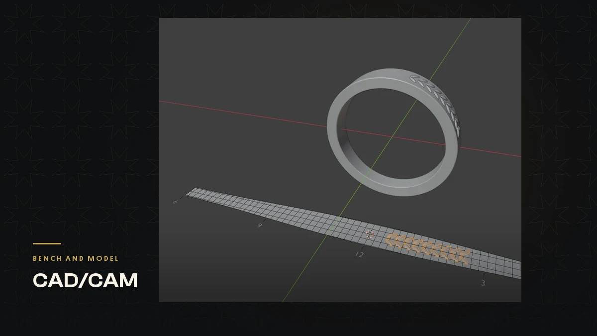
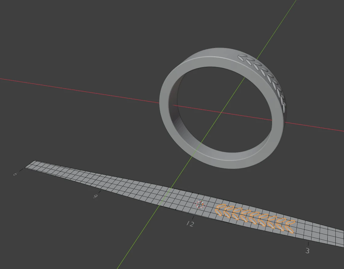
Draw the pattern flat, at true size, on a guide that is the ring’s outer face rolled out, then let a flow tool move every point from the guide onto the ring. Test it before you trust it: marks drawn 1 mm apart should still be 1 mm apart on the ring, and a mark 2 mm wide should still be 2 mm wide. In Blender one geometry nodes group can do the move, and I have wrapped it into my CAD/CAM Jeweller add-on as Flow on Surface, but the checks in this piece work on any flow tool, in Rhino or in Blender.
Why draw it flat
Drawn flat, on a guide at true size, a 2 mm leaf is exactly the leaf you drew, and the flow carries it onto the ring. Rhino users know the routine: CreateUVCrv or UnrollSrf, a flat drawing, then FlowAlongSrf with History. I wanted the same three steps in Blender: make the guide, draw on it, make the result real.
I used Claude, through Claude Code, in a working folder of my own rules, scripts and tests. Claude built the proof, the tool and its tests; I set the aim, said go, and found the failure on my own band.
Prove the method before you build the tool
Claude’s first output was a proof, with no tool yet. It unrolled the outer face of a flat band at UK size M, tapering from 2.4 to 4.4 mm wide, into a flat guide at true size. It drew a wheat pattern of 8,547 points on the guide, and added one geometry nodes group that reads where each point sits on the guide and puts it at the same place on the ring. Then it measured the ring.
Sixty millimetres on the guide came out at 59.99998 mm. A mark 2 mm across came out at 2.000 mm, and a mark 0.5 mm high at 0.500 mm. Only then did I say go.
The tool, and what it checks
The tool has three steps: Make Guide, draw on the guide, Make Real. Anything you draw on the guide shows on the ring at once, and the ring follows while you edit the drawing. The guide also says how true it is. A flat face reads “True size”, meaning every edge is within 0.05 % of its length on the piece. A dome reads something like “Centre true, edges -7.9 %”: the centre line and width are exact and the edges land squeezed by that much. A dome cannot be laid flat without squeeze, in any program, so a good tool tells you how much.
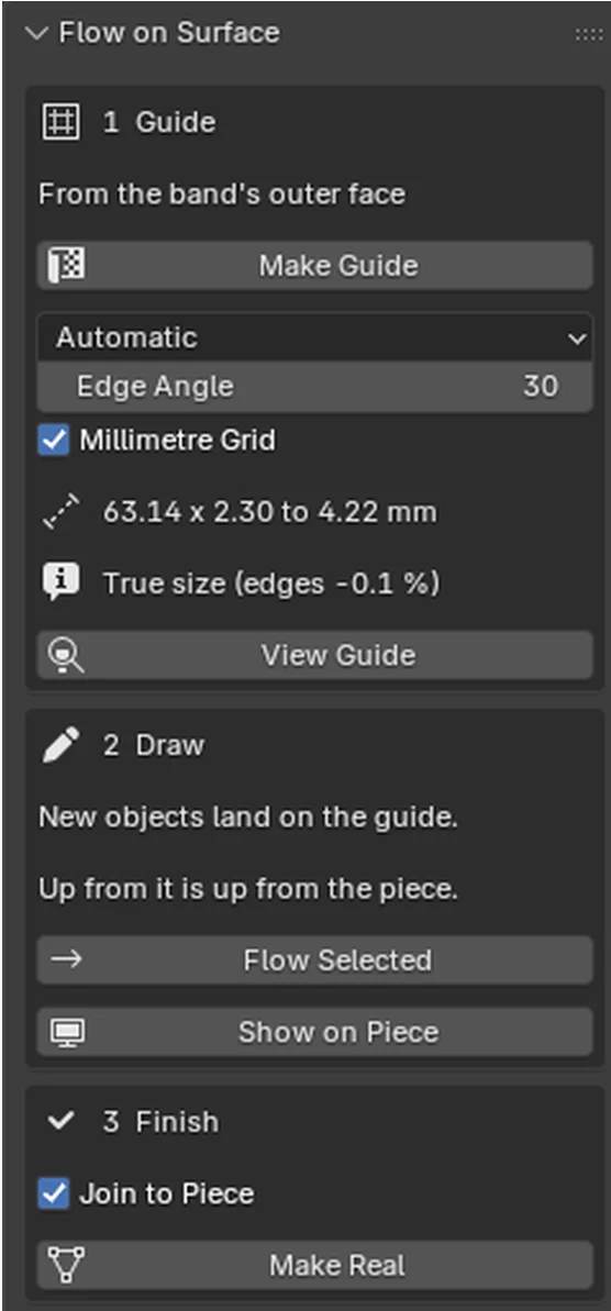
On a UK size M flat band tapering from 2.4 to 4.4 mm, marks drawn 1 mm apart landed within 0.002 mm of their place over 60 mm. 446 automatic tests passed. A wheat band of 112 leaves joined to the band as one closed body, a model that weighs 5.20 g in 18ct at UK size M.
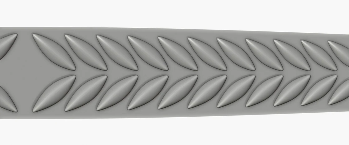
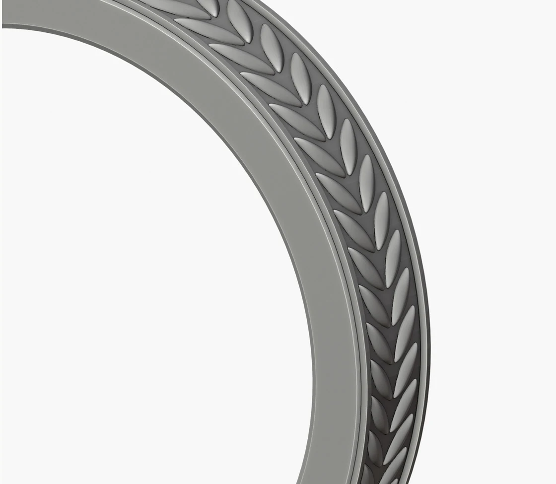
If the pattern does not fuse into one closed solid, the tool puts the band back and says why, for example hollows trapped under the pattern, the kind of pocket a print cannot empty. An early version called 112 leaves with air pockets under them “one closed body”. It now counts loose solids and trapped hollows and says which.
Where it failed
Then I tried it on a band I had pulled into a wishbone shape, with a row of drops drawn on the guide. On the slope, a drop landed sheared by 31 degrees. The guide’s own line had already shown the damage: “Centre true, edges -64.2/+23.8 %”.
Claude reproduced it on a copy of my file, measured the landed drops against the drawn one, and named the cause in numbers. The band had left the round, but the tool still found its sections and rolled the band out round the ring anyway. No single line runs through the middle of a wishbone’s sections, so the roll-out was clamped to their ends. The tests had missed it for a plain reason: picked faces had only been tested on a plain cylinder. A cylinder is round. A wishbone is not.
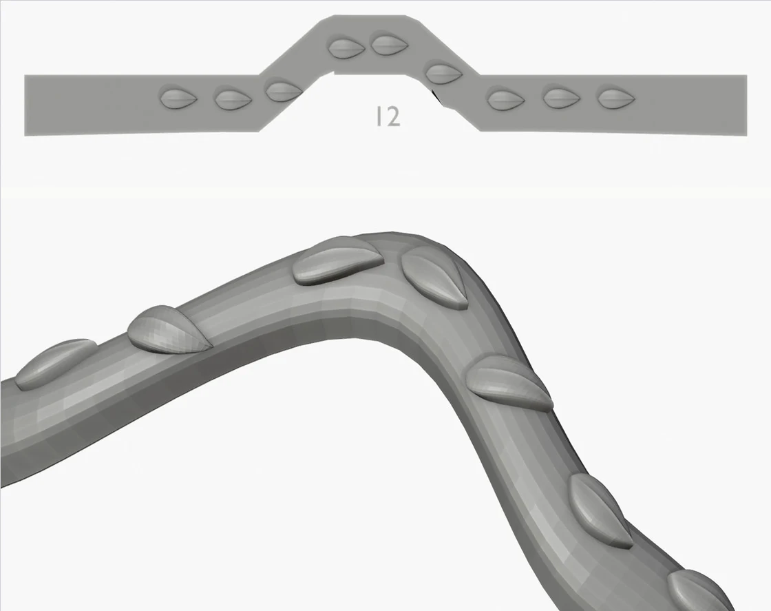
There was a second fault. When I picked the band all the way round, the tool unwrapped it as a loop. A loop cannot lie flat, so the guide came out as a 23 mm disc reading “Lands -36.8 to +137.6 %”.
The fix
The same day the tool was changed in three ways.
-
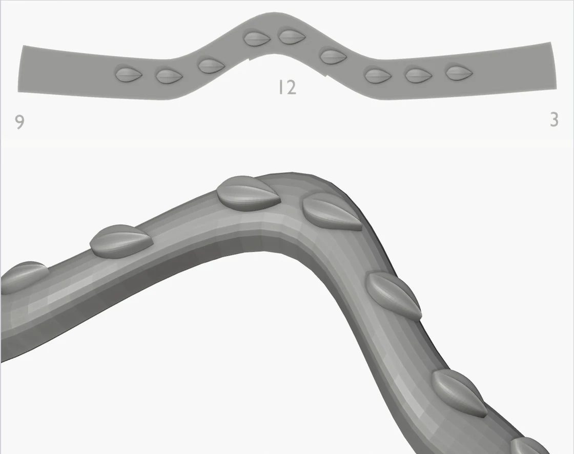
A band pulled out of the round is no longer rolled out round the ring. The tool says “This band has been pulled out of the round” and unwraps it instead, so the guide is the band’s true flat shape. A wishbone lies flat as a chevron, and you draw along the chevron. The same pick now reads “Within 4.8 %, worst +10.5 %”.
-
A band picked all the way round is recognised from how its faces join, and cut open at six o’clock: one strip, 62.67 x 4.81 mm, with 6, 9, 12, 3 and 6 marked.
-
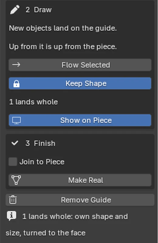
Keep Shape, a new button. A leaf, a scroll or a wire should bend with the surface. A stone, a drop or a setting must not. Select it, press Keep Shape, and every separate piece lands whole, at its own shape and size, turned to the face. Rhino calls this Rigid. Nine of nine drops now land at 1.549 x 0.827 x 0.461 mm, all identical. Left to bend, they ran 1.56 to 1.62 long.
The control
A test is only worth trusting if it can fail. I ran the seven new tests against the first version. All seven fail. With the fix all 453 pass: the 446 from before and the seven new ones.
How to check any flow tool yourself
You need a flat guide, a ring, and a way to measure.
-
Draw 61 ticks exactly 1 mm apart along 60 mm of the flat guide, a mark 2 mm wide and a mark 0.5 mm high.
-
Flow them onto the ring, then measure neighbouring ticks, first tick to last, the width and the height. Mine read 59.99998, 2.000 and 0.500. I call a guide true when every edge is within 0.05 % of its length, which is 0.03 mm over 60 mm.
-
Draw a circle or a round seat and measure two diameters after the flow. If it is no longer round, do not flow stones that way: use the tool’s rigid setting (Keep Shape here, Rigid in Rhino).
-
Test on the worst piece you have, not the best: a band pulled out of the round, a domed face, a picked patch.
-
After any fix, run the new test on the old version. It should fail.
Where the add-on stands
The add-on is a working tool for my students and course members. It is not something I sell. If you would like to try it, subscribe to The Bench Journal at hamedarab.academy, reply to any issue and tell me what you make.